




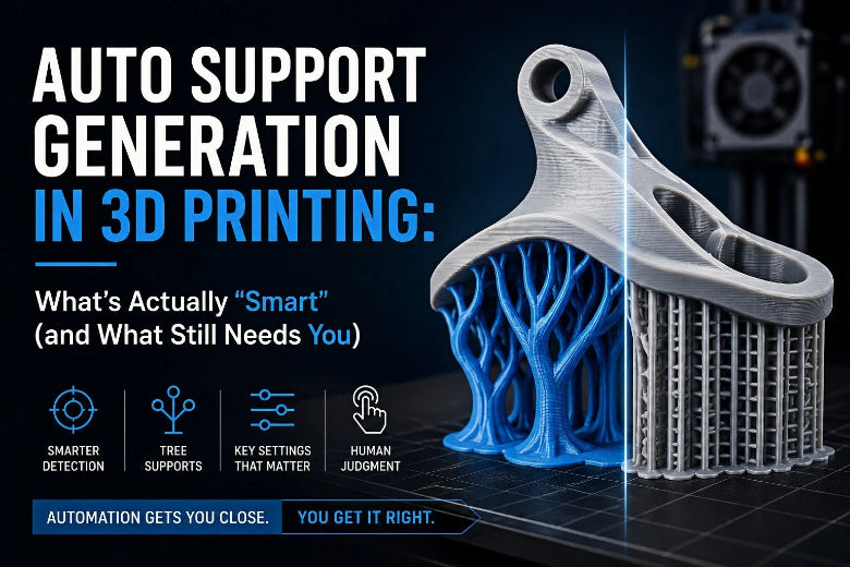
A lot of slicers now market “smart” or “AI-assisted” supports. It has improved—but it’s not magic. The slicer can guess where supports should go; you still decide the trade-offs: surface finish vs removability, print time vs reliability, and how aggressive to be on overhangs.
What “AI-assisted supports” means in slicers (and what it doesn’t)
In practice, “AI-assisted” or “automated” supports in FDM slicers usually means three things:
- Better auto-detection of overhangs (so supports show up where geometry genuinely needs them).
- Tree/organic support algorithms that reduce contact points and material compared to classic grid supports.
- Better manual override tools (paint-on supports, enforcers, blockers) so you can correct the slicer’s guesses quickly.
What it usually doesn’t mean: the slicer understands your priorities.
It doesn’t know which face is cosmetic, whether you’d rather sand than risk a failed print, or whether that 46° overhang is “fine” on your PLA profile but a mess in PETG.
Key Takeaway: Auto supports often get you most of the way there. The last stretch is choosing the right support style and tuning the “separation vs finish” settings.
Why auto support generation matters more on modern (fast) FDM printers
As printers get faster, marginal overhangs stop being forgiving, and the hidden costs of supports show up fast: more filament, more print time, more cleanup, and more chances to knock something loose mid-print.
If you print functional prototypes or small batches, supports are also a workflow problem—every extra minute of removal and cleanup compounds.
The 5 knobs that matter most in auto support generation 3D printing (and the trade-offs they control)
There are dozens of support settings, but most of your real-world wins come from a short list.
1) Overhang threshold: stop supporting “just in case”
Overhang thresholds decide when the slicer should generate supports at all. Setting this too aggressively is how you end up with supports everywhere: more scars, more cleanup, more time.
A better mindset is:
- Support the geometry that truly needs it (long flats, sharp ledges, delicate details).
- Let the printer handle “borderline” overhangs when your material + cooling profile can do it.
If you’re unsure, do a quick sanity check in preview: if the slicer is supporting tiny cosmetic slopes that already print clean on your machine, raise the threshold.
2) Top contact Z distance (Z gap): your main “removal vs finish” dial
This is the vertical gap between the part and the supports.
- Smaller Z gap → better supported undersides, but supports can fuse and leave scars.
- Larger Z gap → easier removal, but undersides sag and look rough.
Prusa’s official documentation explicitly frames this as a key lever (top contact distance) and even suggests a starting range based on layer height (see the Prusa “Support material” guide (2025)).
(We’ll refer to that Prusa guide by name later in this post—no need to open the same link twice.)
If you print PETG a lot, you’ll feel this one immediately: a gap that works in PLA can turn into welded supports in PETG.
3) Support interface layers and interface spacing: a cleaner underside without “support brick” density
Support interfaces are the denser layers right under the part (the “contact patch” zone).
If you care about underside quality, it’s usually smarter to tune interfaces than to crank global support density.
- More support interface layers / tighter interface spacing can reduce sagging.
- But too aggressive interfaces can increase fusing and make removal miserable.
PrusaSlicer documents these settings directly (top/bottom interface layers and spacing) in the same official support reference above.
4) Support painting / enforcers / blockers: where “smart” supports become reliable
Auto support generation is a starting point. Manual control is how you stop wasting time.
Use manual control when:
- supports are touching a cosmetic face
- auto supports miss a narrow internal ledge
- tree branches keep “choosing” bad contact points
- supports appear under areas that print fine without them
Even a quick pass of “block here, enforce there” can cut cleanup time more than any density tweak.
5) Support style: classic vs tree/organic is a geometry decision
Two quick rules that hold up across slicers:
- Tree/organic supports are great when you want fewer contact points on complex geometry.
- Classic/grid/snug supports are often better for broad, flat undersides where you need stability.
If your tree supports keep missing targets or wobble, switching styles can be the fastest fix.
OrcaSlicer support settings: what to check first
OrcaSlicer gives you a lot of control—especially around how supports are generated.
Start with the support mode, not the micro-settings
OrcaSlicer distinguishes between different support generation modes and styles. If you haven’t looked at these in a while, scan the OrcaSlicer support settings overview and make sure you’re using the mode that matches your intent.
Practical workflow: auto supports for coverage, then manual tools (paint/enforce/block) to keep supports off the surfaces you care about.
If you’re using tree supports, tune stability before density
Tree supports are supposed to be efficient. When they fail, people often respond by increasing density everywhere—which makes them harder to remove without necessarily fixing the root problem.
This is where tree supports 3D printing starts to feel like a different skill than “normal supports”: you’re tuning branch geometry (reach + stability), not just infill density.
Orca’s own tree parameter reference is a good map of what each knob actually does (see the OrcaSlicer tree support settings reference). In plain terms:
- Branch diameter / tip diameter: thicker tips and branches are more stable, but leave bigger contact marks.
- Branch distance: closer branches increase stability (and contact frequency).
- Branch angle: more horizontal reach can help “catch” features—but can get wobbly.
If branches are snapping or missing small ledges, try this order:
- Make branches slightly more stable (diameter/tip).
- Reduce overreach (angle) if branches are “reaching into space.”
- Only then increase density or interface aggressiveness.
PrusaSlicer organic supports: what to check first
PrusaSlicer keeps the UI relatively clean, but the support system is still deep.
Pick the right style (Grid vs Snug vs Organic)
Prusa’s official support reference describes three styles:
- Grid: stable and predictable.
- Snug: better at following the overhang shape, often with less “leaking” to walls.
- Organic: branch-like supports intended to be easy to remove and less scarring.
That’s straight from Prusa’s official “Support material” guide (2025).
If organic supports are leaving weird contact points, don’t immediately abandon them—first check whether your contact Z distance and interface settings are tuned for your material.
Don’t ignore the “boring” settings
Prusa’s doc calls out exactly the settings people tend to skip:
- top contact Z distance
- interface layers
- pattern spacing
- XY separation
If supports are hard to remove, small adjustments to Z distance and interface spacing often beat any big change to overall density.
A quick workflow to tune supports without wasting a weekend
If you want a repeatable approach (without turning this into a full tutorial), use this loop:
- Orient the model to keep supports off cosmetic faces.
- Slice with auto supports at a moderate threshold.
- Preview and identify only the overhangs that truly need help.
- Block supports where they’ll scar visible surfaces.
- Enforce/paint supports where auto generation missed critical ledges.
- Adjust one dial at a time: overhang threshold or Z distance or support interface layers/spacing.
If you’re switching materials (PLA → PETG, PETG → TPU), re-check Z gap and interface behavior.
Pro Tip: When you’re chasing easier removal, change Z gap first. When you’re chasing a cleaner underside, change interface layers/spacing first.
FAQ
Why do my supports fuse to the part?
Usually: the contact Z distance is too small for your layer height/material, or your interface is too dense. PETG is especially prone to sticking.
Why does the underside sag even though supports are there?
Usually: the Z gap is too large, or the interface isn’t providing enough “near-solid” surface under the first supported layer.
Why do organic/tree supports sometimes miss an overhang?
Tree/organic supports prioritize fewer contact points and material efficiency. Tight internal geometry, long horizontal reach, or thin branches can cause them to miss or wobble. In OrcaSlicer, branch angle/distance/diameter settings are the stabilizers (see the Orca tree settings reference linked above).
Should I use “supports everywhere”?
Only when you know the geometry demands it (and you can tolerate cleanup). Otherwise, it tends to create scars in places you didn’t need supports in the first place.
Key takeaways
- “AI-assisted supports” mostly means better automation plus better manual override tools—not a perfect one-click solution.
- The biggest levers are overhang threshold, contact Z distance, and support interface layers/spacing.
- Tree/organic supports shine on complex geometry, but classic supports can be better for broad flat undersides.
- The fastest way to improve supports is often: auto-generate → preview → block/enforce → tune one knob.
Next steps
- If you’re setting up a new printer profile (or importing one), start from official presets before you tune supports. SOVOL keeps firmware and slicer profile downloads on its downloads page.
- For SOVOL profiles and configuration files (useful when you’re switching materials/nozzles), see the SV08 sections for SV08 slicing software and configuration files and SV08 material + nozzle profiles.
- If you’re using OrcaSlicer, having a clean base profile helps support tuning behave predictably—especially across materials and nozzle sizes.