




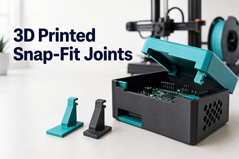
3D printed snap-fit joints eliminate extra hardware by building flexible locking mechanisms directly into your CAD model. A well-designed snap-fit allows two plastic components to click together smoothly, hold securely under load, and disengage easily when needed.
Designing clips for fused deposition modeling (FDM) 3D printing requires a different approach than traditional injection molding. FDM parts are anisotropic, meaning their strength varies depending on layer line direction. Without proper clearances, filleted roots, and correct print orientations, 3D printed clips frequently snap during their very first assembly cycle.
This design guide breaks down the engineering principles behind reliable snap fit 3D printing. You will learn how cantilever flexure geometry works, how to choose the right FDM filaments, and how to calibrate your CAD models for high first-pass printing success.
2. Main Types of Snap-Fit Joints
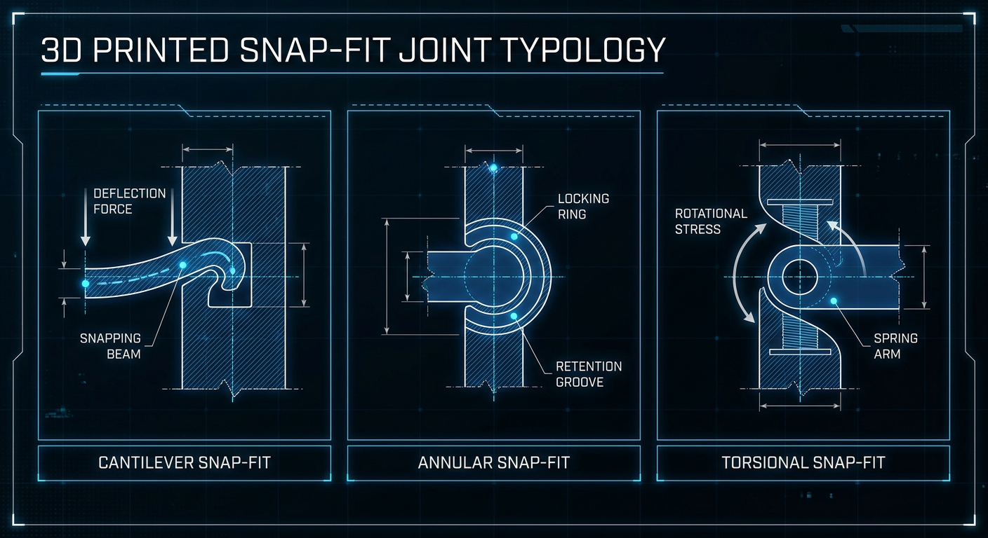
Snap-fit joints rely on the brief elastic deformation of a flexible member as it slides over a retaining lip before springing back into a locking pocket. Matching the right clip style to your enclosure geometry determines both assembly ease and structural holding power.
Cantilever Snap-Fits
The cantilever snap fit is the most widely used style in FDM snap-fit design. It consists of a straight or tapered beam anchored at one end with a hooked overhang at the free tip.
As the mating component pushes against the hook's angled lead-in ramp, the beam deflects outward. Once the catch clears the mating ledge, the arm springs back to its resting state, locking the parts together. Cantilever clips are ideal for rectangular electronics enclosures, battery doors, and sliding panel latches because their bending mechanics are straightforward to calculate and orient on the print bed.
Annular Snap-Fits
Annular snap-fits feature a continuous circular ridge on a cylindrical shaft that engages with an internal mating groove inside a tube or cap. Assembly requires the outer ring to expand or the inner cylinder to compress uniformly around its full perimeter.
Because hoop strain distributes stress radially, 3D printed annular snaps require ductile materials and strict dimensional accuracy. They work well for circular battery caps, press-fit hose adapters, and pen-style caps. However, FDM stair-stepping along curved Z-axis walls can increase friction, making annular joints harder to calibrate on small desktop printers.
Torsional Snap-Fits
Torsional snap-fits replace simple beam bending with torsional twisting. Instead of flexing a beam, pressing the release catch twists an integral cross-bar axis in torsion, pivoting the locking hook away from the catch.
Torsional joints excel in push-to-release buttons, spring-loaded hinged lids, and tool storage latches. Because the main torsional bar can be made longer to distribute strain across a wide cylindrical axis, torsional snaps suffer less flex fatigue than rigid cantilever arms when printed in stiff filaments.
Key Takeaway: Cantilever snaps are the easiest clips to design, orient, and tune for FDM printing. Use annular snaps for cylindrical enclosures and torsional snaps for spring-loaded push buttons.
3. Key Design Rules for FDM Snap-Fits
Successful 3D printed clips depend on bending within the material's elastic limit. If bending stress exceeds the filament's yield point, the clip permanently deforms or snaps at the base.
Flexure Length and Thickness
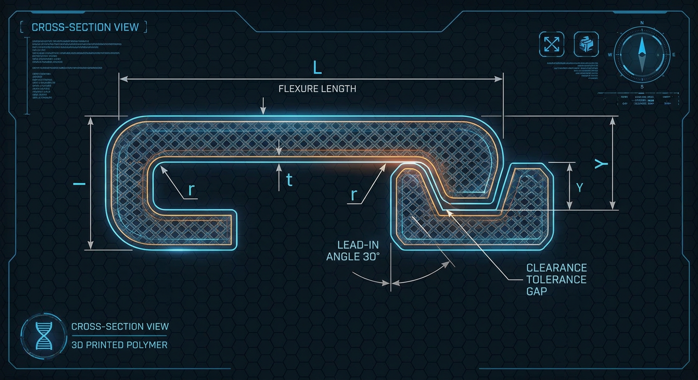
For a cantilever arm under a given load, root bending stress increases with arm length and decreases strongly as beam thickness increases. Deflection also grows rapidly as the arm becomes longer, so the final geometry should be validated with small test coupons.
A practical starting test value for cantilever arms is to aim for a length-to-thickness ratio (L/t) between 8:1 and 10:1 for stiffer materials like PLA, and 5:1 to 8:1 for more ductile materials like PETG. For example, a clip with a 2.0 mm thickness can start with a flexure arm length of approximately 16.0 to 20.0 mm as an initial baseline.
To prevent peak stress from concentrating exclusively at the anchor point, taper the flexure arm's thickness from 100% at the root base down to 50% at the tip. Tapering distributes strain evenly across the entire beam length.
Root Fillets to Reduce Stress Concentration
Sharp internal 90° corners act as stress notches that multiply localized bending forces, making sharp root corners a primary cause of clips breaking during assembly.
Always add a generous fillet radius (r) at the junction where the flexure arm meets the main wall. As a starting test value, the fillet radius should measure between 0.5 and 1.0 times the beam thickness (r ≥ 0.5t), with a recommended minimum starting radius of 0.8 mm to 1.0 mm for standard 0.4 mm nozzles.
Engagement Depth and Undercut
Engagement depth (Y), also called undercut depth, represents how far the hook extends over the retaining ledge. This dimension defines how much the clip must deflect during insertion.
For typical desktop FDM parts, an initial starting undercut depth of 0.5 mm to 1.2 mm usually provides reliable engagement without over-straining the beam. The outer tip of the hook should include a starting lead-in angle of 25° to 35° to convert pushing force into smooth lateral deflection.
Clearance and Tolerance
FDM extrusions suffer from slight dimensional expansion, corner bulging, and first-layer squish. Designing zero-clearance CAD surfaces results in jammed assemblies that fail to flex.
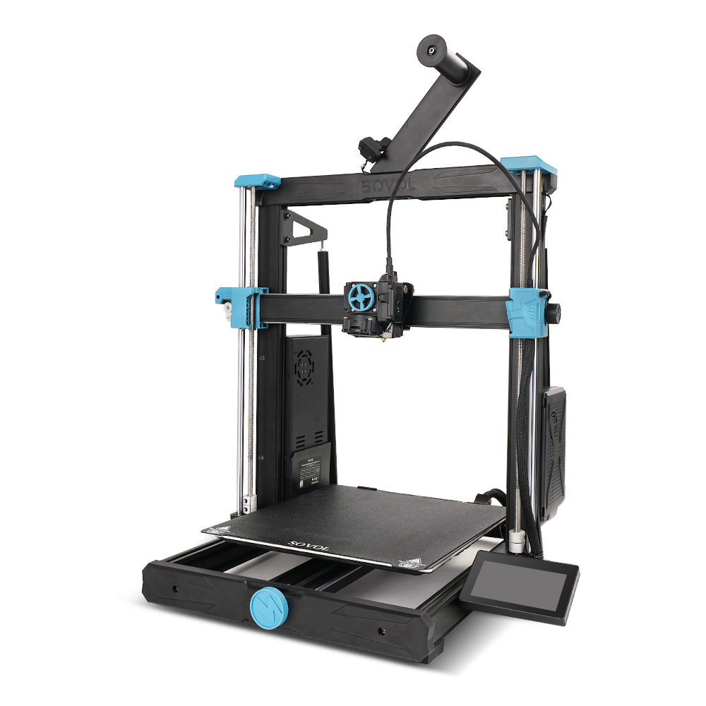
Apply an initial clearance tolerance offset of 0.20 mm to 0.40 mm per side between all non-locking mating faces as a baseline for testing. High-precision printers, such as the Sovol SV08 high-speed CoreXY 3D printer featuring ±0.1 mm printing accuracy and rigid frame mechanics, can hold tight offsets accurately.
Insertion Force and Release Force
The force required to assemble or disassemble a snap-fit joint is controlled by the angles on the hook's faces:
- Insertion Lead Angle (α): Keep this shallow as a starting test value (25° to 35°) so parts slide together with light thumb pressure.
- Retention Catch Angle (β): Use a steeper angle (45° to 70°) for removable clips, or a 90° right angle for permanent, non-removable locks.
Pro Tip: Treat all design dimensions as initial reference baselines. Optimal dimensions depend on your exact nozzle size, filament elasticity, printing speeds, and part geometry.
4. Print Orientation and Layer Strength
Because FDM 3D printing builds parts by stacking melted plastic beads layer by layer along the Z-axis, inter-layer adhesion is inherently weaker than in-plane strand continuity.
How Layer Direction Affects Clip Durability
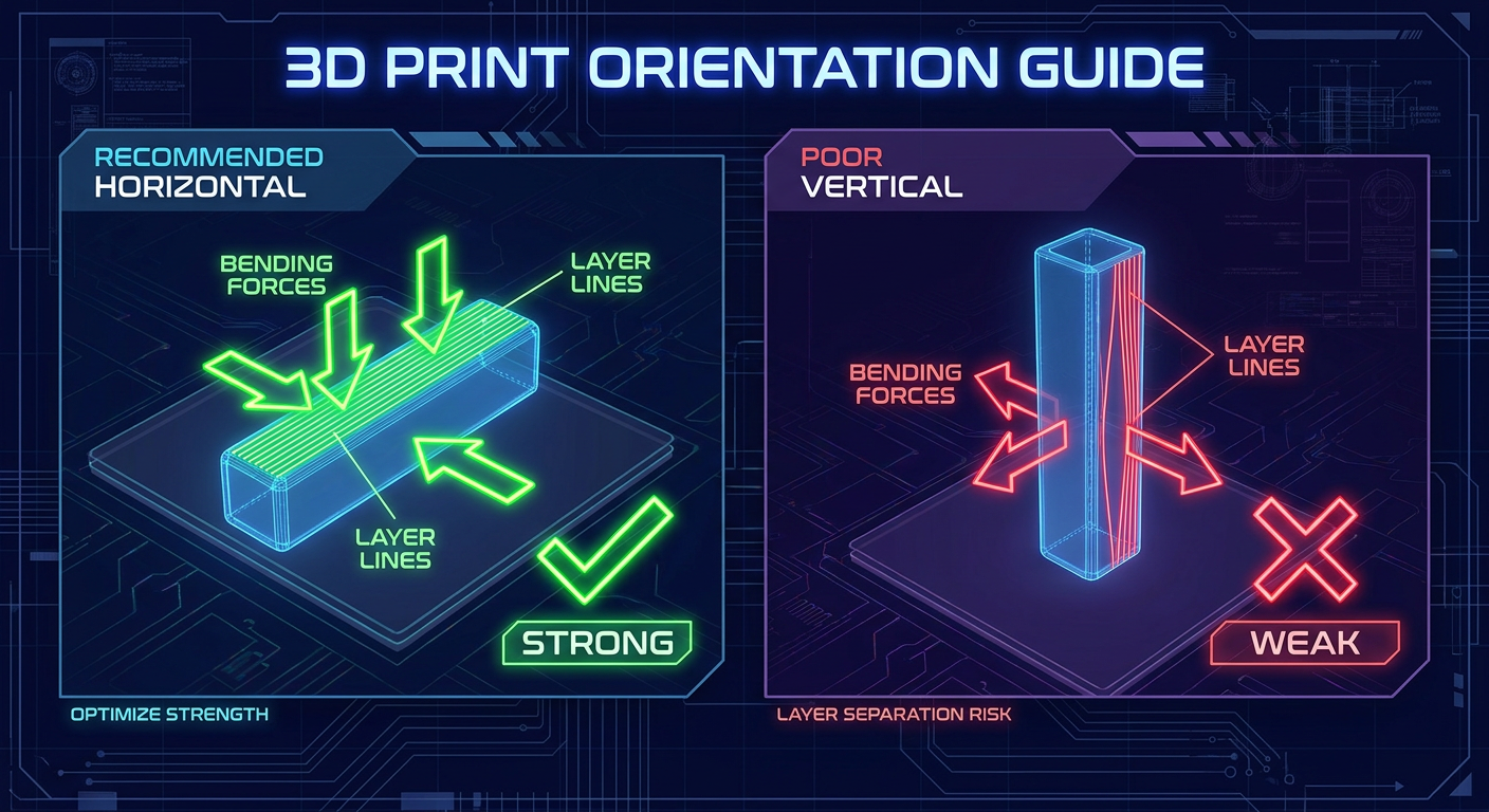
When a clip flexes, tensile forces act along the outer edge of the bending beam. If the cantilever arm is printed vertically upright along the Z-axis, flexing pulls the printed layers directly apart in tension. This causes instantaneous layer separation at the root along the weakest print boundary.
Recommended Flexure Arm Orientation
Always orient the flexure arm flat on the print bed so bending strain occurs parallel to the printed layer lines (in-plane flexure). In this orientation, tensile load is borne along continuous lines of extruded plastic rather than fused inter-layer boundaries.
If your enclosure geometry requires clips on multiple sides, consider printing the clip arms as separate flat-printed insert components that slide into printed dovetail slots on the main body.
5. Choosing Materials for 3D Printed Clips
Material selection dictates flexural behavior, creep resistance, and fatigue life. Mechanical properties vary by formulation and brand; table values represent typical behavior rather than fixed limits.
|
Material |
Flexural Stiffness |
Strain Behavior |
Fatigue & Creep Resistance |
Typical Snap-Fit Use Cases |
|---|---|---|---|---|
|
PLA |
High (Rigid) |
Low strain tolerance |
Moderate; susceptible to creep under load |
Single-assembly locks, light-duty covers, prototype testing |
|
PLA+ / Tough PLA |
High-Moderate |
Improved impact/flex resistance |
Moderate-High |
Functional prototype clips, light enclosure latches |
|
PETG |
Moderate (Ductile) |
Good strain flexibility |
Moderate-High; monitor long-term creep |
Reusable enclosure latches, functional battery doors |
|
ABS |
Moderate-High |
Good strain tolerance |
High |
Temperature-resistant housing latches |
|
ASA |
Moderate-High |
Good strain tolerance |
High (UV Resistant) |
Outdoor structural housings, weather-exposed clips |
|
TPU (95A) |
Very Low (Flexible) |
High elasticity |
High |
Flexible seals, friction-catch plugs, compliant pads |
PLA and PLA+ for Prototypes and Rigid Clips
Standard Polylactic Acid (PLA) offers high tensile strength and minimal shrinkage, making it easy to hold tight CAD tolerances. However, standard PLA is relatively rigid and prone to flex fatigue or creep under continuous load. It works best for initial visual prototypes or permanent single-snap joints. Modified PLA+ formulations offer higher impact strength and flex resistance for light functional clips.
PETG for Repeated Flexing
Polyethylene Terephthalate Glycol (PETG) provides good ductility, strong inter-layer bonding, and higher flexibility than standard PLA. PETG absorbs bending stress well, making it a popular choice for battery doors, tool latches, and reusable enclosure clips, though long-term creep under continuous strain should still be evaluated during testing.
ABS and ASA for Elevated Temperatures and Outdoor Use
Acrylonitrile Butadiene Styrene (ABS) and Acrylonitrile Styrene Acrylate (ASA) combine high impact resistance with elevated thermal performance. ASA adds UV and weather endurance, making it suitable for automotive accessories, drone camera clips, and outdoor sensor housings.
Note: Specific mechanical performance depends heavily on filament manufacturers, additives, and printing parameters. Always test your target filament batch with small test coupons before committing to large prints.
6. Recommended FDM Print Settings
Slicer configuration directly dictates the solid density and structural strength of flexible clip arms.
|
Parameter |
Recommended Starting Baseline |
|---|---|
|
Wall Loops / Perimeters |
3–5 solid shells (starting value) |
|
Layer Height |
0.16 mm – 0.20 mm |
|
Top / Bottom Layers |
4–5 layers |
|
Infill Density |
Thin clip arms are typically solid wall perimeters; for thicker sections, use 30%–100% |
|
Nozzle Diameter |
0.4 mm standard |
|
Support Strategy |
Avoid supports directly on flexible arms where possible |
Wall Loops and Perimeter Shells
Set wall loops (perimeters) to an initial baseline of 3 to 5 shells. For thin flexure arms (1.5 mm to 2.5 mm thick), 4 wall loops often ensure the entire cross-section is composed of continuous concentric shells rather than sparse infill, maximizing flexural resistance.
Layer Height and Cooling
A layer height of 0.16 mm to 0.20 mm provides a solid balance between print speed and inter-layer bonding area. Follow the filament manufacturer's recommended cooling fan and hotend temperature profiles for your specific material to achieve optimal layer fusion.
Support Strategy
Avoid placing slicer support structures directly underneath flexible cantilever arms whenever possible. Support removal scars may create rough stress-raising areas along the tension face that initiate fatigue fractures.
When printing large-scale functional assemblies or multi-part enclosures, high-throughput machines like the Sovol SV08 MAX large-format printer (featuring a 500 × 500 × 500 mm build volume, CoreXY motion system, and up to 700 mm/s print speeds) allow you to arrange multiple snap-fit test iterations side-by-side across a single build plate to evaluate fit rapidly.
⚠️ Warning: Do not intentionally over-extrude (e.g., setting flow rate to 110%) to fix weak clips. Over-extrusion distorts part dimensions, ruins clearance tolerances, and leads to severe binding during assembly. Fix weak clips through geometry and wall loop count instead.
7. Common Problems and Solutions
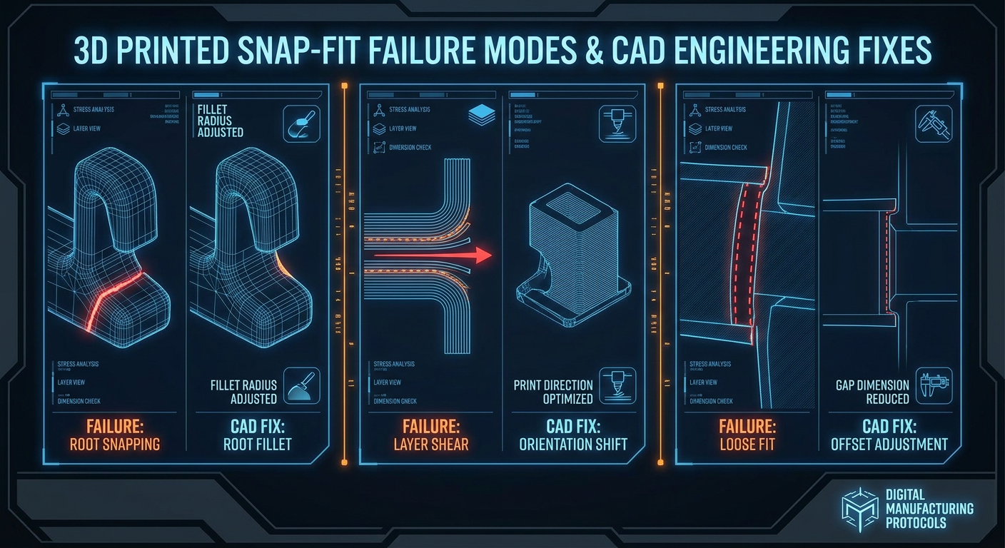
When a 3D printed clip fails during testing, use this practical troubleshooting matrix to identify the root cause and apply the correct CAD or slicer modification.
|
Failure Mode |
Primary Root Cause |
Mechanical Explanation |
Actionable CAD / Slicer Fix |
|---|---|---|---|
|
Clip breaks at the root |
Stress concentration notch or insufficient flexure length |
Bending stress exceeds material yield point at sharp 90° base corner |
Add a generous root fillet (r ≥ 0.5t) and increase beam length (L) to lower peak strain. |
|
Snap-fit is too tight |
Insufficient clearance offset or steep lead-in angle |
Nozzle expansion reduces clearance gap; high insertion force required |
Increase clearance tolerance to 0.30–0.40 mm and decrease lead-in angle to 25°. |
|
Snap-fit is too loose |
Inadequate undercut depth or material creep |
Hook does not extend far enough into retaining pocket; clip loosens over time |
Increase engagement depth (Y) by 0.3–0.5 mm or switch from PLA to PETG/ASA to prevent strain relaxation. |
|
Layers separate during flex |
Poor print orientation (bending across Z-axis layers) |
Tensile forces pull layer boundaries apart in inter-layer shear |
Reorient part flat on bed so flexure occurs parallel to layer lines. |
|
Edges wear down after use |
Abrasion or soft material deformation |
Repeated friction wears down small retaining lip overhangs |
Chamfer mating entry edges and increase catch angle to 60°–70°. |
|
Parts difficult to assemble |
Steeper insertion angle or excessive undercut |
High initial sliding friction prevents smooth entry deflection |
Reduce insertion angle to 25°, apply a material-compatible dry lubricant when appropriate, or taper beam thickness toward tip. |
8. Testing and Iteration Protocol
Designing functional mechanical joints requires empirical verification. Never print a complete 10-hour enclosure before verifying your snap geometry on small test samples.
Snap-Fit Iteration Workflow
- Isolate Joint Geometry in CAD: Export only the clip arm and socket.
- Print Small Test Coupon: Run a quick 15-minute print to verify fit.
- Test Engagement & Retention: Evaluate insertion force and holding power.
- Adjust CAD Parameters: Fine-tune clearance or beam dimensions in 0.05 mm steps.
- Integrate into Full Assembly: Merge the verified joint into your final model.
Calibration Test Coupons
Isolate the snap-fit joint section in your CAD software and export a small test coupon containing just the clip arm and mating socket. A test coupon prints in 15 to 20 minutes, allowing you to validate clearances with minimal filament consumption.
Evaluation Criteria
Evaluate your printed test coupon against four key physical checks:
- Insertion Force: Can the clip engage comfortably with thumb pressure without requiring tools?
- Retention Force: Does the joint hold securely under expected pull loads without slipping open?
- Cycle Fatigue: Disengage and re-engage the clip 20 to 30 consecutive times. Does the clip retain its original spring tension without cracking or permanently bending?
- Dimensional Alignment: Does the mating seam sit flush without visible gaps or rattling?
Adjusting CAD Models vs. Slicer Scaling
If your test coupon is too tight, do not scale the entire model in your slicer. Uniform global scaling scales overall enclosure dimensions, wall thicknesses, and hole diameters simultaneously, ruining alignment across other features.
Always return to your native CAD software and modify the specific geometric feature parameter—such as widening the clearance offset gap from 0.20 mm to 0.30 mm or extending the flexure arm length by 2.0 mm—while keeping overall part dimensions unchanged.
9. Practical Applications for 3D Printed Snap-Fits
Incorporating reliable clips expands what you can create with desktop FDM printers:
- Removable Enclosure Covers: Protect custom PCBs, Raspberry Pi projects, and power supplies with snap-on lids that allow quick tool-less access.
- Electronics Housings: Mount LED controllers, sensor pods, and battery boxes neatly without exposed screw heads.
- Tool Organizers and Wall Mounts: Build modular French cleat brackets, socket holders, and cable management clips that snap securely onto workshop rails.
- Replacement Parts: Recreate broken plastic latches for vacuum cleaner attachments, battery compartment covers, and remote controls.
- Modular 3D Printed Assemblies: Connect large decorative or functional models printed in multiple sections on standard build plates.
For makers looking for technical tutorials, slicer profiles, and community project guides, explore official Sovol 3D printing guides and tutorials.
10. Summary: Designing Clips That Last
Designing reliable 3D printed snap-fit joints comes down to respecting FDM layer mechanics and controlling flexural stress. By starting with cantilever beam proportions (L/t ≥ 8:1), adding root fillets (r ≥ 0.5t), tapering arm thickness, and orienting flexure bending parallel to printed layer lines, you can reduce the risk of clip breakage.
Always incorporate an initial clearance tolerance offset of 0.20 mm to 0.40 mm between non-locking mating faces, choose ductile filaments like PETG for repeated cycling, and validate your joint geometry using small test coupons before printing your final assembly.
With these mechanical guidelines embedded in your CAD workflow, your 3D printed projects will click together cleanly, stay locked reliably, and perform effectively.