




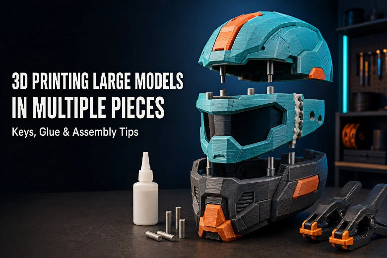
Splitting and assembling models opens up new possibilities for desktop fabrication. It lets you produce objects of virtually unlimited size, optimize individual part orientation for maximum strength, and cut down on wasteful support structures. However, achieving clean joints that remain strong under load requires proper planning. This guide covers how to choose optimal split locations, design alignment features, select adhesives for specific filaments, and finish seams for a professional result.
When Should You Split a Large 3D Model?
Deciding when to split large 3D model files is not just about overcoming build volume limits. Strategic cuts often improve overall print quality and structural reliability in large 3D printing projects.
Build-Volume Limitations
The most obvious reason to divide a model is physical size. When an object's bounding box exceeds your printer's physical build volume, slicing the model into interlocking pieces is the only way to manufacture it at full scale on a desktop machine.
Better Print Orientation
Single-piece prints force you to accept compromise orientations where overhangs, bridges, and strength axes conflict. Splitting allows you to lay each section flat on the build plate. This maximizes layer adhesion along high-stress directions and reduces vertical height, leading to shorter print times and fewer tall-print instability artifacts.
Easier Support Removal
Complex organic models often require massive support structures when printed as one piece. Slicing geometry along flat plane cuts or natural feature contours lets you lay steep overhangs directly against the heat bed, dramatically cutting support material usage and surface scarring.
Reduced Warping and Failed Prints
Large solid prints build up internal thermal stress as thermoplastic layers cool and contract. Slicing expansive models into smaller sections reduces the continuous footprint of each print. This lowers thermal pull on bed adhesion, minimizing corner lift, warping, and multi-hour print failures.
Easier Sanding, Painting, and Transportation
Smaller sub-assemblies fit easily inside sanding boxes, media blasters, or paint booths. If you plan to travel with props, cosplay armor, or trade show displays, modular components with mechanical fasteners or keys make packing and transport far less cumbersome.
How to Choose the Best Split Locations
Where you cut a digital mesh determines how easy the final assembly will be. Placing seams thoughtlessly creates extra bodywork and structural weak points in large 3D printing builds.
Key split strategies to keep in mind:
- Panel Lines & Edges: Hides seams naturally along existing geometry.
- Load-Parallel Cuts: Reduces joint shear forces under mechanical load.
- Flat Recessed Planes: Maximizes surface area for stronger bonding.
Hide Seams Along Natural Edges and Panel Lines
Whenever possible, follow existing geometry features when you split large 3D model files. Align cut planes with mechanical panel gaps, armor seams, belt lines, or sharp changes in surface contour. A joint placed inside an existing groove requires almost no filler, whereas a seam cutting across a smooth flat panel demands extensive filling and sanding.
Avoid Highly Visible Curved Surfaces
Curved organic shapes, such as spherical domes or smooth visors, highlight even microscopic alignment errors. Light reflections catch uneven seams easily. If you must cut across a smooth curve, offset the seam away from primary focal points.
Consider the Direction of Mechanical Loads
FDM prints are anisotropic, meaning tensile strength between printed layers is lower than strength along the continuous filament path. According to the Hubs 3D Printing Technical Guide, joint geometry must be oriented to resist expected operational stresses. Position cut lines parallel to primary load paths rather than perpendicular to them, preventing joint peeling under tension.
Keep Joints Away from Thin or Fragile Areas
Avoid placing cut planes through thin-walled sections or delicate details. Narrow wall profiles offer very little bonding surface area for glue and tend to deform when clamped, resulting in weak connections.
Alignment Features for Multi-Part 3D Prints
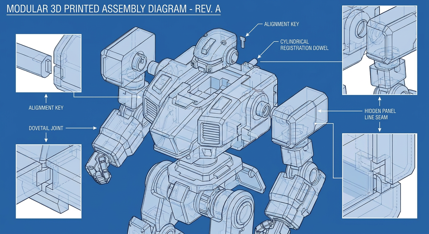
Relying on flat butt joints and glue alone creates major assembly problems. Flat surfaces slide during clamping, causing misalignments that require hours of heavy sanding to correct. Integrated alignment keys 3D printing features lock parts in position during bonding.
Cylindrical Alignment Pins
Cylindrical dowel pins are the simplest registration method. You model matching blind holes into opposing cut faces and insert separate printed or off-the-shelf wooden or metal dowels.
- Pros: Simple to model in CAD or slicers; dowels can be printed horizontally for maximum shear strength.
- Best practice: Use square or D-shaped pins to prevent rotational slipping between round sections.
Dovetail Keys
Dovetails feature trapezoidal keys and slots that slide together along one axis.
- Pros: Provide mechanical interlock that holds parts together even before adhesive cures.
- Best practice: Orient dovetails so the sliding insertion axis remains accessible during assembly.
Tongue-and-Groove Joints
Tongue-and-groove features extend a ridge along the perimeter of one mating face that slots into a matching channel on the opposing piece.
- Pros: Prevents shear slipping in all lateral directions and blocks light transmission through seam gaps.
- Best practice: Keep tongue width at least 1.5 to 2 times your nozzle extrusion width for clean printing.
Flat Registration Surfaces
For smaller non-structural parts, modeling stepped ledges or shallow alignment lip features along the interior wall provides positive location stops without adding separate hardware.
How to Label and Number Parts
When assembling complex models with dozens of sliced pieces, confusion sets in quickly. Model small debossed numbers or identification letters on hidden interior cut faces or alignment pin cavities during slicing to track section order.
Understanding Alignment Clearance and Tolerances
Clearance is the deliberate gap designed between male keys and female cavities to allow parts to slide together smoothly. There is no universal clearance value for every printer and material. When specifying clearance values (such as 0.15 mm to 0.30 mm), always clarify whether the value refers to total clearance or clearance per side.
Clearance requirements vary based on model dimensions, print orientation, machine calibration, slicer settings, and material properties:
- Printer kinematics and physical calibration
- Nozzle diameter, layer height, and line width
- Material thermal shrinkage (ABS contracts significantly more than PLA)
- Slicer flow rate and horizontal expansion settings
Before printing a multi-hour project, print a small fit-test coupon containing your intended pin and hole geometry. Adjust your slicer's horizontal expansion or CAD clearance settings based on the test fit.
Designing Strong Joints
Bonding plastic in large 3D printing requires proper joint engineering. Expanding contact area and eliminating sharp stress risers prevents joints from snapping under load.
Key Takeaway: Joint strength depends on total bonding surface area, surface preparation, load direction, adhesive selection, and print layer orientation. Never rely on smooth layer-skinned butt joints for structural assemblies.
Increase Bonding Surface Area
To connect large 3D printed parts securely, maximize the contact area available for adhesive. Flat butt joints provide minimal surface contact. Inset pockets, overlapping lap joints, or deep registration sockets double or triple the available surface area, dramatically increasing overall shear and tensile strength.
Add Chamfers and Fillets
Sharp 90-degree internal corners concentrate stress and trigger crack propagation. Adding 0.5 mm to 1.0 mm fillets or chamfers to the bases of internal alignment sockets distributes mechanical loads evenly.
Avoid Sharp Stress Concentrations
Avoid notches, sharp step-downs, or acute internal angles along cut planes. Smooth transitions disperse forces throughout the surrounding material rather than focusing stress onto a single printed layer seam.
Leave Room for Adhesive
Glue occupies physical volume. If your male alignment pin fits into its socket with zero clearance, applying adhesive creates hydraulic lock, trapping air and liquid glue and preventing parts from seating completely. Add shallow relief channels or chamfered entry edges on dowel pins so excess adhesive escapes safely.
Design Temporary Alignment Features
For large hollow cosplay props or multi-piece wall displays, design temporary external assembly tabs or internal bolt holes. These features let you draw parts tight with temporary screws or zip ties while glue sets, and can be clipped or filled during post-processing.
Choosing Glue for Different 3D Printed Materials
No single adhesive works equally well on every filament type. Choosing the correct chemical adhesive for your specific thermoplastic determines whether your assembly holds reliably under handling.
As noted in Prusa Research's 3D print assembly guide, mechanical prep combined with proper chemical matching can produce a strong joint for many intended applications.
Cyanoacrylate Glue (CA / Super Glue)
Cyanoacrylate is the standard choice to glue 3D prints for fast assembly. It cures rapidly when reacting with ambient moisture and forms strong bonds across PLA, PETG, and ABS.
- Medium-viscosity CA: Best for smooth, tight-fitting joints.
- CA Gel: Ideal for vertical seams or slightly porous surfaces where liquid glue runs off.
- Limitations: Brittle under impact; offers poor gap-filling capability unless paired with CA accelerator spray.
Two-Part Epoxy
Epoxy resin consists of a resin and hardener mixed in equal ratios. It cures through a thermosetting chemical reaction, creating a high-strength bond.
- Working time: Available in 5-minute, 15-minute, or 30-minute pot life formulations.
- Strengths: Outstanding gap filling and high shear resistance. Epoxy can bond many printed plastics, but performance varies by filament, adhesive formulation, surface preparation, joint geometry, and curing conditions. Always test the exact combination before using it on a load-bearing part.
- Limitations: Requires precise mixing, mechanical clamping, and sufficient curing time before loading.
Plastic Cement and Solvent Welding
Solvent welding works by chemically dissolving the surface layer of compatible thermoplastics, allowing polymer chains to fuse together as the solvent evaporates. Always use products explicitly formulated for your target material, adhere to Safety Data Sheets (SDS) and ventilation guidelines, and test on scrap pieces first.
- ABS and ASA: Can be solvent-welded using acetone or dedicated ABS liquid cements.
- PLA and PETG: Traditional hobby polystyrene cements (such as model airplane glue) will not melt or bond PLA or PETG. Never assume ABS/ASA solvents will work on PLA/PETG. Specialized solvent formulations (such as ethyl acetate) require careful handling and material verification.
Adhesive Selection Matrix for 3D Printing Filaments
Compatibility and strength vary by filament brand, adhesive formulation, surface preparation, and joint geometry. Treat this table as a starting point and test a sample joint before relying on it.
|
Adhesive Type |
Compatible Filaments |
Shear & Impact Strength |
Gap-Filling Ability |
Cure Speed |
Best Use Scenario |
|---|---|---|---|---|---|
|
Cyanoacrylate (CA / Super Glue) |
PLA, PETG, ABS, ASA |
Moderate (Brittle) |
Poor (Requires Gel/Powder) |
Fast (10–60 sec) |
Display models, small parts, quick alignment tacking |
|
Two-Part Epoxy |
PLA, PETG, ABS, ASA, TPU |
High (Tough & Impact-Resistant) |
Excellent |
Slow (5 min to 24 hrs) |
Load-bearing parts, functional tools, uneven joints |
|
Acetone / Solvent Weld |
ABS, ASA (Not PLA/PETG) |
Potentially high, depending on material, solvent, joint design, and prep |
Moderate (Slurry) |
Fast to Medium |
ABS/ASA structural welded assemblies |
|
Material-Specific Solvent |
PLA, PETG, ABS (Exact formula match) |
Varies by formulation |
Poor |
Fast (30–120 sec) |
Use only with exact polymer and product recommended by manufacturer |
Step-by-Step Assembly Workflow
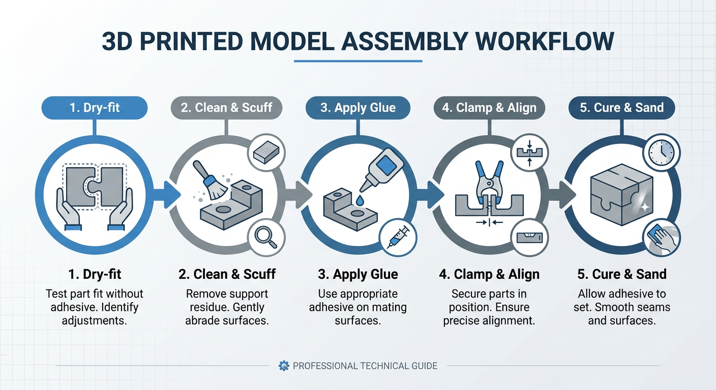
Rushing assembly often ruins hours of careful printing. Follow this sequence for consistent results:
- Dry-Fit: Test fit all printed sections and registration pins.
- Clean & Scuff: Lightly sand bonding faces and clean with IPA.
- Apply Glue: Spread adhesive evenly across internal mating surfaces.
- Clamp & Align: Secure parts tightly with padded clamps or painter's tape.
- Cure: Allow adhesive to fully cure before applying mechanical stress.
- Load Test: Gently test joint integrity before final finishing.
Step 1: Dry-Fit Every Part
Assemble the entire model completely without glue. Check that alignment pins seat fully, seams pull flush, and no internal features bind. If a pin is tight, sand it down now rather than fighting it while glue is setting.
Step 2: Check Alignment and Gaps
Inspect every exterior joint line under bright lighting. Look for light passing through seam gaps or surface stepping caused by minor print warping. Mark areas that require extra clamping or sanding.
Step 3: Clean and Lightly Roughen Bonding Surfaces
Smooth printed bottom layers and glossy top perimeters reduce adhesive grip. Lightly scuff all mating surfaces with 180-grit or 220-grit sandpaper to create micro-texture for mechanical interlocking. Clean away sanding dust and finger oils using isopropyl alcohol (IPA) and allow it to dry completely.
Step 4: Apply Adhesive Carefully
Apply adhesive evenly to interior registration pockets and mating surfaces. Avoid applying excess glue near exterior edges, as clamping will squeeze wet glue onto visible outer surfaces.
Step 5: Clamp or Hold Parts in Position
Apply firm, steady pressure using spring clamps, bar clamps, painter's tape, or ratcheting straps. Always use padded corner blocks or rubber pads between clamp jaws and printed walls to distribute pressure evenly without scarring external surfaces.
Step 6: Allow Sufficient Curing Time
Respect working and full cure times. A 5-minute epoxy may reach handling strength quickly but often needs much longer to reach its stated full cure. Follow the adhesive manufacturer’s cure schedule before applying mechanical loads.
Step 7: Test the Joint Before Applying Load
Once cured, gently apply flex and torsion stress to the joint by hand over a soft surface. Confirm the bond is solid before executing final 3D printed parts assembly steps or mounting heavy hardware.
Hiding Seams After Assembly
Even well-designed multi-part projects show fine seam lines where printed pieces meet. Follow a structured post-processing workflow to achieve a smooth surface finish:
- Gap Filling: Pack seam gaps with appropriate putty or filler.
- Initial Sanding: Level high spots with 180–220 grit sandpaper.
- Filler Primer: Spray high-build primer to highlight remaining micro-imperfections.
- Fine Sanding: Wet-sand with 400–600 grit paper for a smooth finish.
- Paint: Apply final color coats in thin, even layers.
Gap Filling
Fill small seam valleys and pinholes using dedicated gap fillers:
- Two-part epoxy putty: Ideal for deep structural gaps and load-bearing edges.
- Acrylic spot putty / Glazing putty: Perfect for fine hairline seams and minor surface imperfections.
- 3D Pen Filament Welding: Use a 3D pen with matching filament to melt plastic directly into deep seams; this can fill deep seams and may provide local reinforcement, but joint strength should be tested for the intended use.
Sanding Progression
Begin sanding using 180-grit to 220-grit wet-or-dry sandpaper wrapped around a rigid sanding block to level high spots. Progress to 320-grit and 400-grit paper, using light circular motions. If compatible with the filler or primer, wet-sand to prevent plastic dust from clogging sandpaper and melting from friction heat.
Primer Application
Spray a coat of high-build filler primer over the seam area. High-build primer fills micro-scratches and highlights remaining surface dips or pinholes.
Re-Sanding
Allow the primer to dry completely, then lightly sand with 400-grit to 600-grit paper. Repeat filler primer and sanding cycles until the transition between printed parts is smooth enough for the desired finish.
Painting and Preserving Surface Details
Apply your final color coats in thin, even passes. Mask off nearby surface details, panel lines, or recessed textures during heavy sanding so you do not accidentally erase surrounding model features.
Common Problems and Solutions
The following troubleshooting matrix addresses common assembly errors encountered during large 3D printing multi-part builds.
|
Issue |
Likely Cause |
Recommended Solution |
|---|---|---|
|
Misaligned Parts |
Alignment pins printed without sufficient clearance or inserted tilted. |
Ream socket holes with a drill bit; sand down pin sides; dry-fit before applying glue. |
|
Large Gaps Between Pieces |
Print bed warping or thermal contraction lifted corners during printing. |
Fill deep gaps with 3D pen filament welding or 2-part epoxy putty before sanding smooth. |
|
Weak Adhesive Joints |
Unprepped smooth surfaces, incorrect glue for material, or insufficient cure time. |
Scuff mating faces with 220-grit paper, clean with IPA, and switch to two-part epoxy. |
|
Parts Separating During Curing |
Clamps slipped or uneven pressure was applied while adhesive set. |
Use rubberized clamp pads, painter's tape bracing, or rigid assembly jigs to hold alignment. |
|
Visible Seams After Painting |
Incomplete seam filling or shrinkage of solvent-based spot putty. |
Apply high-build filler primer, follow the filler manufacturer’s drying and recoating instructions, re-sand flat, and reapply topcoat. |
|
Warped Mating Surfaces |
Excessive print bed heat or uneven cooling on large flat base layers. |
Block-sand mating faces flat on a sheet of glass before applying adhesive and alignment keys. |
Safety and Handling Tips
Working with adhesives, solvents, and plastic dust requires basic workshop safety measures.
- Ventilation: Always apply CA glues, solvent cements, spray primers, and paints in a well-ventilated area or under a dedicated fume extraction hood. As emphasized in Loctite's 3D print gluing tutorial, avoiding vapor inhalation is essential when working with fast-evaporating chemical bonding agents.
- Eye and Skin Protection: Wear safety glasses and nitrile gloves. Cyanoacrylate bonds skin instantly, and two-part epoxies can cause skin sensitization over time.
- Safe Clamping Practices: Do not over-tighten metal bar clamps on thin-walled hollow prints. Excessive force can crush internal infill structures or snap printed shell perimeters.
- Critical Safety Disclaimer: Do not rely on glued or spliced 3D printed assemblies for load-bearing, structural, overhead, or safety-critical applications (such as climbing gear, automotive structural parts, or heavy load rigging) without professional engineering validation and mechanical fasteners.
Frequently Asked Questions
What is the best clearance for 3D printed alignment pins?
There is no single universal value. Clearance typically ranges between 0.15 mm and 0.30 mm, but you should always specify whether this value refers to total clearance or clearance per side. Because fit is influenced by printer calibration, part orientation, and material shrinkage, always print a small fit-test coupon using your specific filament and slicer settings before committing to a full multi-part build.
Can you glue PLA with model airplane cement?
No. Traditional model airplane cement contains solvents designed specifically for polystyrene plastic. It will not dissolve or bond PLA or PETG. Use cyanoacrylate (super glue) or two-part epoxy for PLA and PETG prints instead.
Is super glue strong enough for functional 3D printed parts?
Super glue (cyanoacrylate) provides strong shear resistance on tight-fitting rigid parts, but it is brittle and can fail under heavy impact or bending loads. Epoxy is often more suitable for uneven joints or impact loads, depending on the product and application.
How do I fill large seam gaps in multi-piece 3D prints?
For deep gaps caused by print warping, use a 3D printing pen with matching filament to weld plastic directly into the seam, or pack the gap with two-part epoxy putty. Once cured, sand the area flush and smooth with acrylic glazing putty and filler primer.
Conclusion
Mastering multi-part large 3D printing allows you to create impressive, large-scale projects on standard desktop equipment. By splitting a model into modular sections, you can create projects far larger than your printer’s build volume while maintaining the strength and finish required for the intended use. Taking the time to dry-fit every joint, clamp securely, and properly fill and sand seams turns separate printed sections into a cohesive finished model.