




Few things in FDM 3D printing are as frustrating as removing a finished print only to find support structures permanently fused to the model. Conversely, using insufficient support causes molten filament to drop into mid-air, leaving ugly drooping loops and ruined dimensional tolerances.
Support structures are a necessary trade-off in fused deposition modeling. Because 3D printers build models layer by layer from the bottom up, plastic cannot be deposited on thin air. However, default slicer support profiles are intentionally conservative—designed to prevent print failures at the expense of surface finish and easy removal.
Whether you are printing detailed models or functional engineering components on a high-speed machine like the Sovol SV08 high-speed CoreXY 3D printer, tuning your 3D printing support settings allows you to achieve clean underside surfaces while snapping off supports effortlessly.
This guide breaks down overhang mechanics, compares tree supports vs normal supports, details parameter values for popular filaments, and provides a troubleshooting framework for Sovol 3D printer support settings.
What Are 3D Printing Supports and When Are They Necessary?

In FDM 3D printing, molten plastic is extruded onto the build plate or a previously printed layer. As long as a new layer rests sufficiently on the layer beneath it, plastic cools without sagging. When a feature extends outward into empty space without underlying support, it forms an overhang or a bridge.
The 45-Degree Rule and Overhang Mechanics
The Rule of 45 Degrees serves as a practical baseline for FDM printing, though actual limits depend on material, cooling, layer height, and print speed:
- 0° to 45° Overhangs: Typically printable without supports under standard cooling conditions.
- 45° to 60° Overhangs: The transition zone where part cooling and reduced print speeds determine success.
- Overhangs Exceeding 60°: Angles past 60° usually require support structures as gravity overcomes plastic viscosity.
Bridging Limitations: When Gaps Fail Without Support
Bridging occurs when the printer extrudes plastic between two solid anchor points across empty space. Bridge profiles may adjust bridge speed, flow, and cooling as a starting baseline to freeze strands in mid-air.
Short bridges (under 10–15 mm) span successfully on well-calibrated machines. However, as bridging distance exceeds 20 mm, filament sags without adequate support.
Tree Supports vs Normal Supports: Choosing the Right Structure
Modern slicing software offers two main geometric algorithms for generating support scaffolding. Evaluating tree supports vs normal supports is key to optimizing speed, material consumption, and surface finish.
Tree (Organic) Supports: Material Savings and Easy Removal
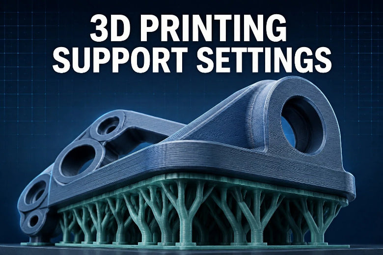
Tree supports generate hollow, trunk-like structures that branch out from the build plate and curve around your model to reach specific overhang contact points.
Pros:
- Minimal Contact Area: Touches the model only at small contact tips, drastically reducing surface scarring.
- Build Plate Anchoring: Avoids placing support bases directly on top of printed model surfaces.
- Filament Efficiency: Can reduce material usage compared to traditional grid structures depending on geometry and slicer settings.
- Rapid Removal: Branches snap off cleanly without needing heavy tools.
Cons:
-
Can be less stable on extremely tall, top-heavy prints during high-acceleration travel moves.
Normal (Grid/Snug) Supports: Rigidity for Large Ceilings
Normal supports generate solid vertical pillars directly beneath overhangs in a repeating grid or rectilinear pattern.
Pros:
- High Structural Stability: Ideal for heavy, flat, wide horizontal ceilings (e.g., electronic enclosures or mechanical brackets).
-
Predictable Columns: Less prone to swaying during rapid travel moves.
Cons:
- Higher Material Waste: Dense vertical columns consume significant filament.
- Difficult Removal: Grid structures often lock tightly into inner cavities.
Comparison Matrix
|
Feature |
Tree (Organic) Supports |
Normal (Grid / Snug) Supports |
|---|---|---|
|
Best Use Case |
Organic models, figurines, complex functional parts with angled overhangs |
Large, flat horizontal ceilings, rectangular boxes, heavy mechanical components |
|
Material Consumption |
Low (Saves 30%–50% filament) |
High to Moderate |
|
Removal Effort |
Very Easy (Snaps off cleanly) |
Moderate to Difficult (Requires pliers in tight spots) |
|
Surface Finish |
Excellent (Minimal point contacts) |
Good to Fair (Can leave line marks across wide roofs) |
|
Print Speed Impact |
Faster total print time |
Slower print time due to higher volume |
The 4 Critical 3D Printing Support Settings for Flawless Surface Finish
Fine-tuning parameters is essential for achieving cleaner 3D prints. Four core settings control the interface mechanics between support structures and your model.
1. Support Contact Z Distance: The Removability Key
The support z distance (or Top Contact Z Distance) is the single most critical parameter for learning how to remove 3D printing supports easily. It defines the vertical air gap between the top of the support roof and the bottom layer of your model.
- Too Small (under 0.10 mm): Hot extruded plastic fuses directly into the support layer, welding them together.
- Too Large (over 0.35 mm): The overhang layer drops through the air gap without making contact, causing sagging.
- Optimal Rule: Set support z distance to 1.0× to 1.5× your layer height. For a standard 0.20 mm layer height, a Z clearance of 0.20 mm to 0.30 mm provides the ideal balance between support contact and effortless release.
2. Support XY Distance: Preventing Side-Wall Fusion
While Z distance handles vertical clearance, Support XY Distance controls horizontal clearance between vertical walls and adjacent support columns.
- Recommended Range: 0.40 mm to 0.60 mm (100%–150% of a standard 0.4 mm nozzle diameter).
- A setting of 0.50 mm ensures support branches remain independent from vertical feature walls while remaining close enough to support adjacent overhangs.
3. Support Interface Layer and Density
A dedicated support interface layer is a dense roof constructed at the top of the support column, directly below the model overhang. Instead of supporting your print on a sparse 10% infill grid, the slicer lays down 2 to 3 solid layers to create a flat ceiling.
- Support Interface Layers: Set to 2 to 3 layers.
- Support Interface Density: Set to 75% to 100%.
- Interface Pattern: Use Concentric for Tree supports or Rectilinear for Normal supports.
By creating a solid roof, the overhang layer lays flat across a smooth plane. Because the contact Z air gap sits directly above this interface, the entire roof pops off cleanly in one piece.
4. Support Density and Infill Patterns
The body of a support structure does not need to be solid. A support body infill density of 10% to 15% is more than sufficient to hold up the interface layers while conserving filament.
Material-Specific Support Presets: PLA, PETG, TPU, ABS, and ASA

Filaments exhibit distinct thermal expansion and bonding properties. A support configuration that works for PLA will fail or fuse permanently when applied to PETG or TPU.
Recommended Settings Matrix
The table below provides practical starting-point settings for a 0.4 mm nozzle and 0.20 mm layer height across major FDM material families:
|
Filament Type |
Contact Z Distance |
Support XY Distance |
Interface Layers |
Interface Density |
Recommended Support Type |
|---|---|---|---|---|---|
|
PLA / PLA+ |
0.20 mm (1.0× layer height) |
0.45 – 0.50 mm |
2 – 3 layers |
80% – 100% |
Tree (Organic) |
|
PETG |
0.28 – 0.30 mm (1.5× layer height) |
0.60 – 0.80 mm |
2 layers |
70% – 85% |
Tree or Normal |
|
TPU (Flexible) |
0.30 – 0.40 mm (1.5×–2.0× layer height) |
0.80 – 1.00 mm |
1 – 2 layers |
50% – 70% (Interface Density) |
Tree (Minimize supports!) |
|
ABS / ASA |
0.20 – 0.24 mm (1.0×–1.2× layer height) |
0.50 – 0.60 mm |
2 – 3 layers |
85% – 100% |
Normal or Tree |
Tailoring Clearance to Filament Adhesion Behavior
- PLA: Rapid cooling and moderate inter-layer adhesion allow a 1:1 ratio between layer height and support z distance (0.20 mm gap for a 0.20 mm layer height).
- PETG: PETG bonds aggressively to itself. Increase support z distance to 0.28–0.30 mm and open up XY distance to 0.60 mm to prevent welding.
- TPU: Flexible filaments bend rather than snap. Supports inside tight cavities in TPU are difficult to extract. Always minimize supports, reduce support body infill density to 5%–10% while keeping support interface density around 50%–70%, and expand Z clearance to at least 0.30 mm.
- ABS / ASA: Chamber cooling and material shrinkage may affect support adhesion, but results vary and warping must be monitored carefully. Keep Z clearance around 0.20–0.24 mm with a 15% support base density.
How Print Orientation Reduces Support Requirements

The most effective support setting is the one you don't have to use. Re-orienting your model in slicing software before printing alters overhang angles, reduces support volume, and hides support contact marks on cosmetic faces.
Rotating Models to Minimize Overhang Surface Area
Consider a mechanical bracket shaped like the letter "T". Printed upright, the horizontal crossbar forms two massive 90-degree overhangs, requiring extensive support scaffolding.
By simply rotating the model 90 degrees onto its back, the "T" profile lays flat against the print bed. Overhangs are completely eliminated, print time drops, and zero support material is consumed.
Key orientation strategies include:
- The 45-Degree Tilt: Tilting tall vertical components by 45 degrees converts flat 90-degree ceilings into self-supporting 45-degree slopes, keeping your 3D printing overhang angle within safe limits.
- Hiding Contact Marks: Position critical cosmetic or functional surfaces facing upward, placing supports on hidden bottom faces.
- Teardrop Hole Profiling: Replacing round horizontal hole tops with teardrop shapes allows holes to print cleanly without internal supports.
Advanced Techniques: Zero-Gap Supports and Multi-Material Workflows
For functional components requiring improved surface quality on bottom overhangs, multi-material 3D printing workflows solve surface texture limitations.
Leveraging Dissolvable and Breakaway Interface Materials
When using multi-extruder or multi-material systems, you can print the main body out of one material (e.g., PLA) and the support interface layer out of an incompatible or dissolvable material.
- Soluble Supports (PVA / BVOH): Polyvinyl Alcohol (PVA) dissolves in water, helping reduce surface damage when properly calibrated. Note that PVA and BVOH are highly hygroscopic and require thorough active drying before use, as well as lower chamber temperatures to prevent heat creep degradation.
- Incompatible Material Interface (PLA + PETG): PLA and PETG can sometimes be used as a low-adhesion interface combination, but results vary by brand, temperature, cooling, and slicer settings. Test a small interface sample before using zero-gap supports on a final print.
High-Speed CoreXY Printing Considerations (Sovol SV08 Focus)
Modern high-speed 3D printers—such as the open-source Sovol SV08 high-speed CoreXY 3D printer—feature maximum rated travel speeds up to 700 mm/s and accelerations reaching 40,000 mm/s². High-speed inertia creates unique challenges for supports, and actual support printing usually benefits from more conservative baseline speeds:
- Support Interface Speed: Slower support interface speeds (e.g. 50–100 mm/s) provide a solid starting point to ensure clean extrusion roofs.
- Tree Branch Stability: Increase tree support trunk diameter in Klipper slicer profiles to ensure tall branches don't wobble under rapid direction changes and travel moves.
- Z-Hop on Travel: Enabling a 0.2–0.4 mm Z-hop during travel serves as a starting baseline to prevent nozzle collisions with thin support tips, though keep in mind Z-hop may increase travel stringing and total print time.
Common Support Problems and Troubleshooting Solutions
Use this diagnostic guide to troubleshoot support issues on your build plate:
1. Supports Fused to the Model / Unremovable
- Causes: Contact Z distance is too small; print temperature is too high; insufficient part cooling.
- Fixes: Increase support z distance by +0.04 mm increments; expand XY distance to 0.60 mm; reduce nozzle temperature by 5°C–10°C.
2. Sagging or Rough Bottom Overhang Surfaces
- Causes: Contact Z distance is too large; missing support interface layers; support density is too sparse.
- Fixes: Decrease support z distance by -0.04 mm increments; enable 2–3 support interface layers at 85%–100% density.
3. Support Structures Toppling Mid-Print
- Causes: Thin support base; high acceleration travel collisions; poor bed adhesion.
- Fixes: Enable a 3–5 mm Support Brim; switch to Tree supports; enable Z-hop on travel.
Practical Pre-Print Support Checklist
Before sending your file to your Sovol open-source FDM 3D printer, run through this 7-point pre-print check:
- Overhang Inspection: Did you rotate the model to minimize overhangs exceeding 60 degrees?
- Support Geometry Selected: Are you using Tree (Organic) for complex geometries or Normal (Snug) for large flat ceilings?
- Contact Z Distance Calibrated: Is Z distance set to 1.0×–1.5× layer height (0.20 mm for PLA, 0.28 mm for PETG)?
- XY Clearance Verified: Is Support XY Distance set to 0.50 mm or higher?
- Interface Roof Enabled: Are 2 to 3 interface layers configured at 75%–100% density?
- Filament Adhesion Matched: Did you increase clearance for sticky materials like PETG and TPU?
- First Layer Anchor Secure: Is a support brim enabled for tall support trees on high-speed machines?
Next Steps for Cleaner FDM Prints
Mastering your 3D printing support settings transforms FDM 3D printing into a repeatable, high-precision process. By tuning Z distance, XY clearance, and interface roofs to your specific filament, you achieve pristine surface finishes and hassle-free post-processing.
Pairing calibrated slicer settings with reliable hardware like Sovol open-source FDM 3D printers ensures consistent, high-quality results on every build.
Frequently Asked Questions (FAQ)
What Are the Best 3D Printing Support Settings for Clean Removal?
The best configuration for clean support removal is setting the support z distance to 1.0× to 1.5× your layer height (e.g., 0.20 mm to 0.30 mm gap for a 0.20 mm layer height in PLA), paired with 2 to 3 dense support interface layers (80%–100% density) and an XY separation of 0.50 mm.
When comparing tree supports vs normal supports, which is better?
Use tree supports for organic models, figurines, and complex functional parts—they touch the model at minimal points and snap off easily while reducing material usage. Use normal supports for large, wide, flat horizontal ceilings or heavy mechanical enclosures that need maximum vertical pillar rigidity.
How much support z distance should I set for PETG?
Because PETG bonds strongly to itself, set support z distance to 0.28 mm – 0.30 mm (for 0.20 mm layer height) and open the XY distance to 0.60–0.80 mm. Using standard PLA Z clearances on PETG will weld the supports permanently to your model.
How to remove 3D printing supports without damaging the model?
To know how to remove 3D printing supports cleanly, ensure you have set a proper contact Z gap and dense interface layer in your slicer. After printing, let the build plate cool completely. Use flush cutters or needle-nose pliers at the base of the support branch and twist gently—properly calibrated supports will snap off cleanly along the interface gap.