




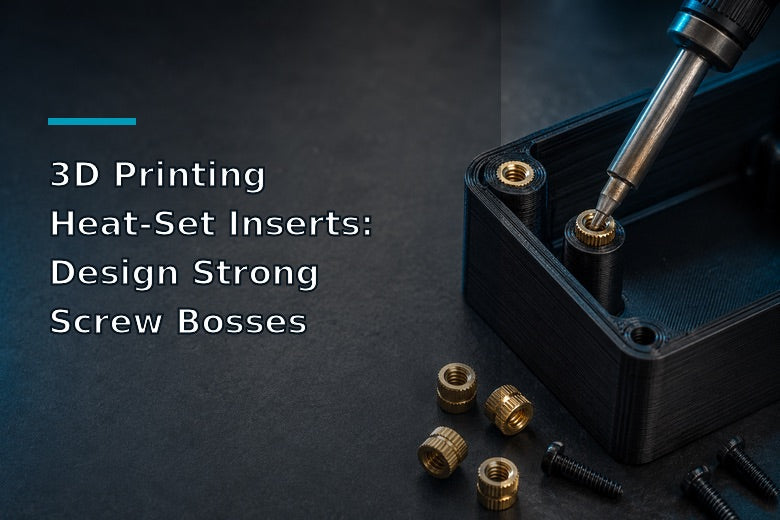
Mastering 3D printing heat-set inserts solves this durability problem. By pairing brass heat-set inserts with properly designed CAD boss geometry, you can create strong, reusable machine threads inside 3D-printed enclosures, custom brackets, sensor mounts, and production fixtures. This guide explains how brass heat-set inserts work, how to design a robust 3D printed screw boss, slicer settings that maximize pull-out strength, step-by-step thermal installation, and how to troubleshoot common failures.
Key Takeaway: Heat-set inserts transfer mechanical loads from soft thermoplastic to durable brass threads. Success depends on CAD boss geometry, slicer perimeter thickness, and controlled thermal installation.
What Are Heat-Set Inserts?
Brass heat-set inserts are cylindrical, internally threaded metal bushings engineered for installation into thermoplastic parts. Their outer surface features opposing helical knurls and retention grooves.
When heated with a soldering iron, brass heat-set inserts transfer thermal energy into the surrounding plastic. As the plastic reaches its softening point, it flows into the knurls and undercut grooves. Upon cooling, the plastic re-solidifies around the brass geometry, locking the insert securely in place.
This process offers three distinct advantages:
- Standard Machine Threads: Internal threads fit standard metric or imperial hardware (such as M2, M3, M4, or M5 hex bolts).
- Superior Load Distribution: Broad outer knurls distribute clamping torque across a larger volume of plastic.
- Repeated Assembly: Steel screws mate against solid brass rather than soft plastic, which can support repeated assembly when properly designed and installed.
3D Printing Heat-Set Inserts vs. Other Fastening Methods
Choosing the right fastening method depends on functional requirements, disassembly frequency, and part geometry.
|
Fastening Method |
Reusability |
Pull-Out Resistance |
Best Use Case |
|---|---|---|---|
|
Heat-Set Inserts |
High (Repeated) |
High |
Enclosures, structural brackets, removable lids |
|
Printed Plastic Threads |
Limited |
Low |
Large decorative caps, low-torque covers |
|
Self-Tapping Screws |
Moderate |
Moderate |
Permanent assemblies, low-cost prototypes |
|
Snap-Fit Joints |
Moderate |
Low to Moderate |
Battery doors, light cover plates |
|
Captive Hex Nuts |
High |
Very High |
High-load structural frames, slotted profiles |
Ratings are general tendencies for comparable designs, not guaranteed performance values. Actual strength and reusability depend on insert geometry, boss design, material, print settings, installation quality, and applied load.
Printed Threads
Printing internal threads directly into FDM parts is typically easier to achieve reliably in larger fastener sizes (such as M8 or larger), as nozzle diameter, layer height, material choice, and print orientation heavily impact fine thread quality. For smaller sizes like M3 or M4, standard extrusions often struggle to reproduce sharp profiles without custom calibration.
Self-Tapping Screws
Thread-forming screws cut their own mating threads into a raw hole. While quick for simple covers, repeated removal strips the plastic bore, leaving a loose joint that cannot maintain clamping force.
Snap-Fit Joints
Snap-fits eliminate extra hardware but require precise cantilever calculations. They are prone to fatigue failure over time, especially in rigid materials like PLA or carbon composites.
Captive Hex Nuts
Captive nut pockets lock standard hex nuts inside printed slots. They offer high pull-out strength but require larger physical footprints and specific print orientations to prevent nuts from slipping out during assembly.
When to Choose Heat-Set Inserts: Use heat-set inserts whenever your project requires high clamping force, compact mounting footprints, vibration resistance, or frequent disassembly—such as 3D printed enclosure screws holding sensitive electronics or modular brackets.
How to Design a Strong 3D-Printed Screw Boss
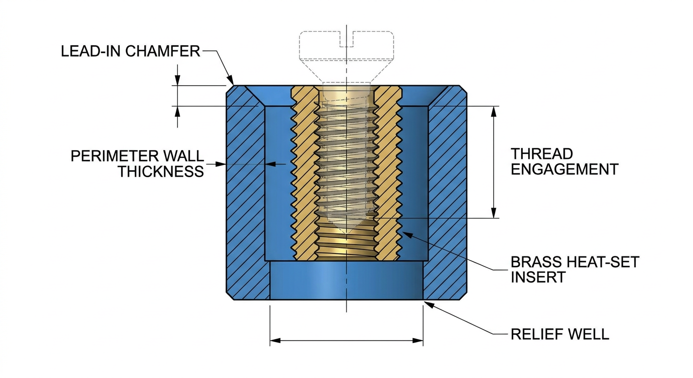
A screw boss is the cylindrical plastic feature designed to house an insert or fastener. Designing a strong 3D printed screw boss requires following specific geometric proportions tailored to your hardware and filament.
Note: All dimensions in this section are starting points, not universal specifications. Always follow the insert manufacturer’s datasheet and validate the fit with a test coupon.
1. Select Hardware First
Procure your brass heat-set inserts and measure their exact length and outer knurl diameter before starting CAD modeling. Insert dimensions vary between suppliers—an M3 insert from one manufacturer may have a 4.2mm outer diameter, while another uses 4.6mm.
2. Follow Manufacturer Hole Sizing
Never use a single universal hole value. As a general starting baseline, recommended heat-set insert hole sizes in CAD are often 0.1mm to 0.3mm smaller than the insert's major knurl diameter, but you should always consult the insert manufacturer's datasheet and verify on a test coupon. This interference fit is intended to help softened plastic fill the knurl grooves without cracking the boss.
3. Maintain Adequate Wall Thickness
The plastic wall surrounding the hole must withstand thermal expansion during insertion and hoop stress during screw tightening. Use these starting reference guidelines as a baseline for testing:
- Boss Outer Diameter: Aim for an initial total boss outer diameter roughly 1.5× to 2× the insert outer diameter.
- Solid Wall Rule: A starting reference value of ~2.0mm of solid plastic wall surrounding the insert hole works well for standard M3 or M4 fasteners. For higher loads, consider increasing wall thickness after testing.
4. Keep Bosses Away from Thin Outer Walls
Placing a screw boss too close to an enclosure's outer wall creates thin plastic regions. Thermal energy from the soldering iron can bleed through, causing cosmetic bulging or melting straight through the exterior surface. Keep the outer edge of the boss at least 1.5mm to 2.0mm away from thin outer walls and sharp edges.
5. Add a Lead-In Chamfer
Add a small 0.5mm to 1.0mm × 45° chamfer at the top entrance of the hole. This chamfer guides and centers the insert before heat is applied, preventing crooked installation.
6. Add Fillets and Gussets at the Base
Tall, unsupported bosses act as levers. Applying side loads or tightening screws can snap an unsupported boss off at its base plate. Add generous fillets (R1.5mm to R3.0mm) where the boss meets the wall, or add triangular support gussets for tall standoffs.
7. Account for Screw Depth and Relief Wells
Design the blind pilot hole 0.5mm to 1.5mm deeper than the length of the insert. This relief well collects excess molten plastic so it does not block lower internal threads or cause screws to bottom out before clamping parts together.
8. Perimeter Count Over Infill
Infill patterns provide volume but contribute very little to insert retention. The mechanical pull-out strength of a heat-set insert depends primarily on the number of solid perimeters surrounding the hole. High infill alone cannot compensate for weak outer walls.
Design Tip: Set wall thickness and perimeter counts so the boss wall around the insert consists of 100% solid concentric extrusions with zero infill gaps.
CAD and Slicer Settings That Affect Insert Strength
Print orientation and slicer parameters directly affect how much force an installed insert can sustain before pulling out or shearing plastic.
Print Orientation and Layer Direction
FDM prints are anisotropic; bond strength between layers is weaker than strength along extruded filament lines.
The strongest print orientation depends on the actual load case. Axial pull-out, shear, and bending can stress the boss differently, so do not treat vertical or horizontal holes as universally stronger. Print a small test coupon in the intended orientation and compare fit and retention before committing to the final part.
Slicer Perimeter Count
As a starting reference, set your slicer's perimeter count (walls/shells) to 4 to 6 perimeters around the screw boss feature. This helps ensure the boss wall is printed as solid concentric rings for strong knurl engagement.
Layer Height and Speed
- Layer Height: Standard layer heights (such as 0.16mm to 0.20mm) promote dense layer bonding and smooth hole walls. Coarse layers on small bosses can reduce contact surface area.
- Print Speed: Setting slicer speed for Small Perimeters to a moderate starting speed (e.g. 20–30 mm/s) helps ensure round, accurate pilot holes without corner cutting, though exact speeds depend on printer calibration.
- Supports: Use supports only when overhang geometry requires it, keeping the interior of the boss hole clear.
Test Coupons and Slicer Preview
Before printing a complete enclosure, print a small test coupon (a block with 3–4 boss variations) to verify hole dimensions and insert fit. Check the hole and insert alignment in your slicer preview to confirm continuous perimeters surround the hole.
Note: Slicer values vary based on printer calibration, nozzle diameter, and filament brand. Treat numerical settings as test ranges rather than universal defaults.
How to Install Heat-Set Inserts Step by Step
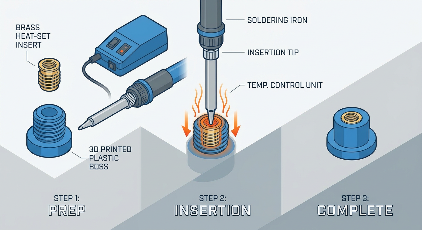
Learning how to install heat-set inserts correctly ensures clean, vertical threads and strong mechanical joints.
Recommended Tools
- Temperature-controlled soldering iron.
- Dedicated heat-set insert tip (or smooth conical tip).
- Flat metal block (for pressing inserts flush).
- Heat-resistant surface and safety glasses.
Step-by-Step Installation Workflow
- Print and Clean the Part: Print the part with the designed pilot hole and verify the bore is free of stringing or debris.
- Select the Iron Tip: Mount an installation tip matching your insert thread size onto your soldering iron. Insert manufacturers generally recommend using a tip sized specifically for the insert so thermal energy transfers cleanly into the metal body to soften the surrounding plastic without damaging internal threads.
- Set Iron Temperature: Set a temperature-controlled soldering iron according to the insert manufacturer’s instructions and the filament’s softening behavior. The correct setting depends on the insert geometry, tip, plastic type, and dwell time. Start with a test coupon and use the lowest temperature that seats the insert cleanly without scorching or deforming the boss.
- Align the Insert: Place the brass insert flat into the top lead-in chamfer of the hole. Check vertical alignment from two angles to ensure it sits upright.
- Apply Gentle Vertical Pressure: Insert the heated tip into the center of the brass insert. Apply light downward pressure, letting heat melt the plastic smoothly.
- Stop at Correct Depth: Ease up on pressure as the top face approaches flush. Remove the iron tip when the insert sits slightly (~0.2mm) above the surface.
- Cool Before Tightening: Immediately press the flat face of a cool metal block against the insert for a few seconds to push it perfectly flush and draw heat away. Allow the plastic to cool completely before tightening a screw.
Common Installation Mistakes to Avoid
- Pressing Too Quickly: Forcing the insert down before plastic melts creates mechanical pressure that splits the plastic boss.
- Installing at an Angle: Tipping the iron results in crooked threads that bind mating panels.
- Melting Through Thin Walls: Excessive dwell time in bosses placed near thin outer walls melts through exterior surfaces.
- Pushing Too Deep: Sinking the insert past flush deforms the upper rim and forces plastic into internal threads.
- Using Excessive Heat: Overheating burns polymer chains, leaving brittle, weak plastic around the insert.
- Tightening Too Soon: Threading a screw into a warm insert pulls the brass straight out of soft plastic.
⚠️ Safety Note: Soldering irons operate at temperatures capable of causing severe burns. Work in a well-ventilated space to handle light polymer fumes, wear eye protection, and use tools to handle warm brass components.
Material Considerations
Thermoplastics differ in thermal conductivity, glass transition temperature (Tg), and melt viscosity.
PLA (Polylactic Acid)
- Behavior: Low glass transition temperature (~60°C). Softens rapidly when touched with a warm iron.
- Considerations: Forgiving for testing, but easy to overheat. Use the lowest effective temperature and short contact times to prevent boss deformation.
PETG (Polyethylene Terephthalate Glycol)
- Behavior: Higher heat resistance (Tg ~80°C) and higher melt viscosity than PLA.
- Considerations: PETG yields slightly under stress, making bosses less prone to brittle cracking than PLA. Fine-tune iron heat based on test prints.
ABS and ASA
- Behavior: Higher glass transition temperature (around 100°C–105°C) and good thermal stability.
- Considerations: ABS and ASA flow cleanly around knurls when properly heated, creating strong mechanical interlocks once cooled.
Nylon and Engineering Materials
- Behavior: Higher melting points and stiff mechanical matrix. Nylon filaments are also hygroscopic and absorb moisture if un-dried.
- Considerations: Stiffer filled filaments (like PA-CF or PET-CF) flow less readily into knurl undercuts. If a test coupon shows excessive interference or boss cracking, try a slightly larger pilot hole in small increments. Do not assume a fixed offset for every filled filament.
Testing Recommendation: Material softening and shrinkage vary by brand. Always test your heat-set insert hole size and installation temperature on a small sample print before installing inserts into a final enclosure.
Common Problems and Fixes
Use this troubleshooting matrix to resolve heat-set insert installation issues.
|
Problem |
Likely Cause |
Practical Fix |
|---|---|---|
|
Insert spins inside the boss |
Hole is oversized, wall is melted, or insert was overheated. |
Reduce hole size in CAD in small increments; add perimeters; lower iron temperature. |
|
Boss cracks during installation |
Hole is undersized, wall is too thin, or insert was forced cold. |
Increase hole diameter in CAD; increase wall thickness in small increments; let heat do the work. |
|
Insert sits too deep |
Excessive downward pressure applied; no depth relief stop. |
Stop pressing slightly above surface and press flush with a metal block; lower temperature. |
|
Insert is installed at an angle |
Iron applied off-axis; missing lead-in chamfer. |
Add a lead-in chamfer in CAD; use a vertical guide jig or dedicated iron tip. |
|
Screw does not fit |
Plastic melted into internal threads; wrong thread pitch used. |
Clean threads with a tap; use dedicated tip with pilot stem; recheck screw thread pitch. |
|
Screw bottoms out before clamping |
Pilot hole depth is too shallow or screw is too long. |
Increase relief well depth below insert in CAD; shorten screw length or add a flat washer. |
|
Boss pulls out under load |
Insufficient perimeters; insert installed parallel to load path. |
Increase perimeters based on test results; test different orientations to match load path. |
|
Plastic melts through the outer wall |
Boss placed too close to exterior wall; iron held too long. |
Move boss away from thin outer walls; reduce dwell time and iron heat based on test prints. |
|
Insert hole is too loose or too tight |
Printer dimensional inaccuracy; uncalibrated flow rate. |
Tune slicer horizontal hole expansion compensation; print a multi-hole test coupon first. |
Practical Design Applications
Heat-set inserts transform custom 3D prints into functional hardware across key design applications:
- Electronics Enclosures: Housing PCBs and microcontrollers requires frequent access. Heat-set inserts in corner standoffs allow lids to be fastened securely with flush machine screws without stripping plastic.
- Camera and Sensor Mounts: Adjustable camera mounts undergo constant positioning. Using brass heat-set inserts at pivot points enables reliable clamping force without crushing printed arms.
- Tool Holders and Fixtures: Workshop jigs and toolhead accessories benefit from modular interfaces. Threaded inserts allow quick accessory swapping using standard hex bolts.
- Replacement Parts & Brackets: Rebuilding broken commercial brackets with custom 3D printed parts and heat-set inserts provides a durable mounting solution.
- Small-Batch Products: Functional small-batch parts can achieve clean, reusable threaded joints when properly designed and tested.
Heat-Set Inserts on Sovol Printers
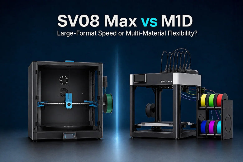
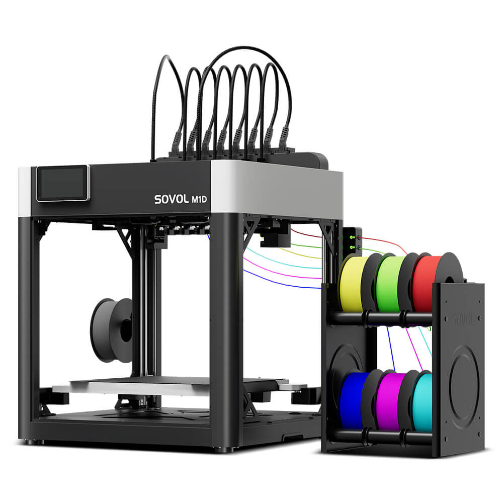
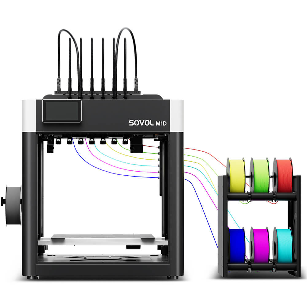
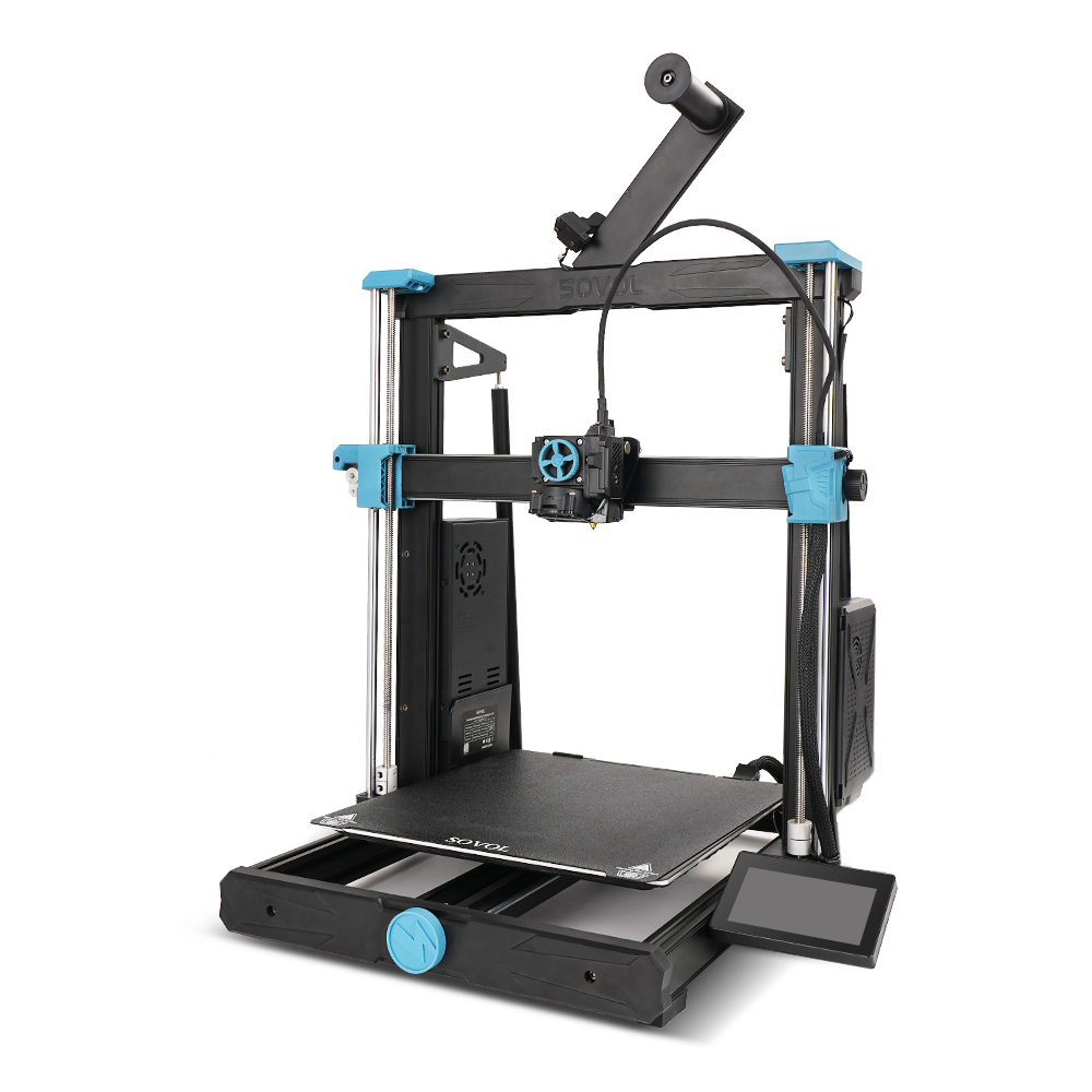
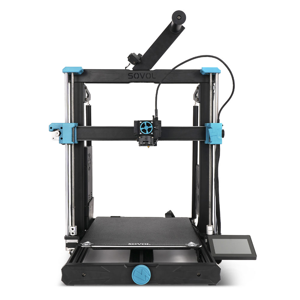
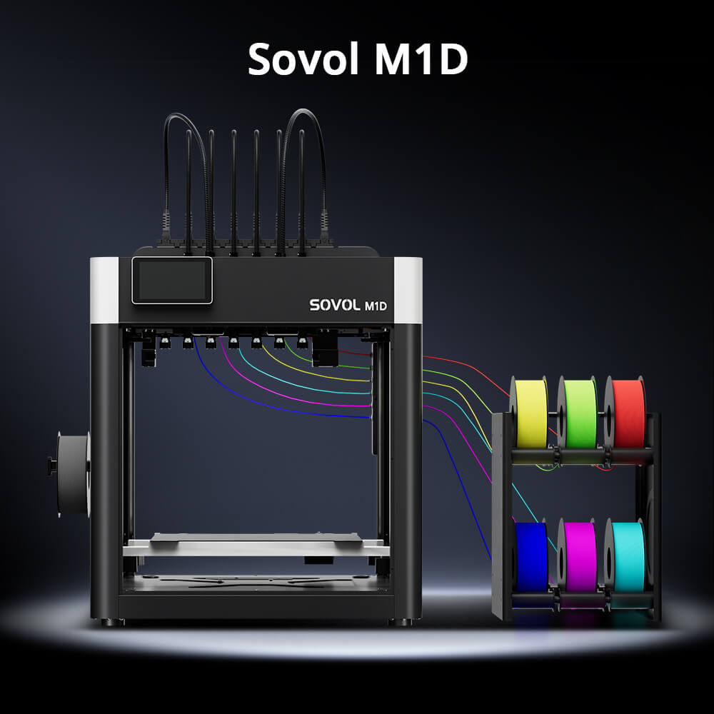
Printing functional parts with suitable hole tolerances requires a properly calibrated 3D printer. Open-source desktop FDM printers—such as the Sovol SV08, Sovol SV08 MAX, Sovol Zero, and Sovol M1D—provide a versatile platform for prototyping test coupons and iterating functional parts.
- Prototyping Pilot Holes: High-speed CoreXY printers like the Sovol SV08 (350×350×345mm build volume) and SV08 MAX (500×500×500mm build volume) offer large build areas and direct-drive extruders suitable for rapid testing of boss geometries and hole dimensions.
- Material Selection: For materials such as ABS, ASA, and composite filaments, use an enclosure or printer configuration appropriate for the material and follow the printer and filament manufacturer’s recommendations.
- Desktop Iteration: Compact printers like the Sovol Zero allow makers to quickly test different hole sizing coupons before printing final enclosure components.
Note: Final hole accuracy and insert retention strength depend on machine calibration, slicer settings, material shrinkage, and careful thermal installation. Always verify critical tolerances on test prints first.
Conclusion
Mastering 3D printing heat-set inserts upgrades custom 3D prints into durable, professional assemblies.
- Geometry Matters: Design screw bosses with adequate wall thickness around the hole, lead-in chamfers, base fillets, and relief wells below the insert.
- Prioritize Perimeters: Increase continuous perimeters around boss features so brass knurls engage solid plastic rather than sparse infill.
- Controlled Installation: Set iron temperature according to manufacturer instructions and material behavior, apply light vertical pressure, and let thermal conduction seat the insert smoothly.
- Test First: Always print a multi-hole test coupon to verify hole sizing and installation temperature before printing final parts.
By combining sound CAD boss design with careful thermal installation and test coupon validation, you can create 3D-printed products that handle their intended loads after suitable testing.