




Before anything else: run a simple tolerance test before you print your final part. The numbers below are starting points, not guarantees — your actual fit depends on printer, nozzle size, layer height, extrusion flow, cooling, and material. Here's how to design parts that fit the first time, and how to fix the ones that don't.
Key Takeaway: Clearances are starting points. Verify them with a quick tolerance test on your own printer and material before committing hours to the real part.
3D Printing Tolerances vs. Clearances: What's the Difference?
Tolerance is how far a printed dimension can drift from the value in your CAD model. Every FDM printer has one. Industry references like Hubs' guide to dimensional accuracy in 3D printing put desktop FDM at roughly ±0.5% with a floor around ±0.5 mm — and on a well-calibrated machine you can usually hold roughly ±0.2 to ±0.5 mm in practice. The real number for a given part depends on its size, geometry, and how the surfaces are oriented on the build plate.
Clearance is the gap you deliberately leave between two parts that must fit together — and dialing in the right FDM clearance is the step people skip most often. If you model a 10 mm pin and a 10 mm hole as the exact same size, the printed parts likely won't slide — internal holes tend to print slightly undersized (a slicer effect known as arc compression pulls the filament inward as it traces a circle). The solution isn't to shave the pin; it's to size the hole larger than the pin by the amount of clearance your joint needs.
So the mental model is simple: tolerance is what your printer adds or subtracts from every dimension; clearance is the design buffer you add so parts still fit despite that drift.
Fit Types: Sliding, Press, Snap, and Moving Parts
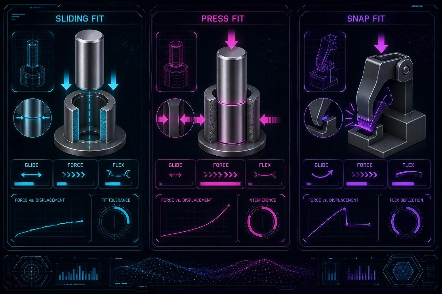
Different joints need different amounts of clearance. Here's a practical starting point, expressed as clearance per side (per side, not total diameter), for a typical 0.4 mm nozzle with well-tuned flow.
|
Fit type |
Starting clearance (per side) |
What it feels like |
Typical use |
|---|---|---|---|
|
Press fit |
0.05–0.15 mm |
Needs firm push; friction holds it |
Bearings, dowel pins, heat-set bosses |
|
Sliding fit |
0.2–0.3 mm |
Moves freely with minimal wobble |
Lids, drawers, guides, pistons |
|
Snap fit |
0.3 mm+ plus designed flexure |
Deflection does the latching, not the gap |
Clips, caps, battery covers |
|
Moving / print-in-place |
~0.3–0.4 mm total |
Rotates or slides without fusing |
Hinges, articulated joints |
A few notes before you rely on this table.
- Press fits are the most sensitive — and where press-fit 3D printing goes wrong most often. On a material that shrinks a lot (like ASA), a nominal 0.1 mm press can end up far tighter than intended. If you want a press fit that holds but isn't glued solid, start small and test a sample couple.
- Snap fits are driven by how far the flexure must deflect, not by the clearance gap alone. Getting the arm geometry, wall count, and flex distance to line up is the real work — the clearance is only part of it. For the full picture on latches and cantilever arms, see our snap-fit joints design guide.
- Moving parts printed in place have the extra constraint of staying separate during printing. Because the first layer squishes sideways, the clearance right at the build plate can fuse. Our print-in-place design guide deep-dives that.
Starting Clearance Ranges for PLA, PETG, and ASA
Because materials shrink and warp differently as they cool, you'll want slightly different clearances for each. The ranking is consistent: PLA is the most dimensionally stable, PETG is a step up in sensitivity, and ASA is the most prone to shrinkage and warping.
|
Material |
Dimensional stability |
Suggested starting clearance (sliding fit, per side) |
Best practice |
|---|---|---|---|
|
PLA |
Excellent |
0.15–0.25 mm |
Easy to dial in; good part cooling helps |
|
PETG |
Good |
0.2–0.3 mm |
Slightly stringy; check first-layer squish |
|
ASA |
Fair (warp-sensitive) |
0.25–0.35 mm |
Enclosure + controlled cooling strongly recommended |
These are only starting points. Results vary by printer, nozzle size, layer height, extrusion flow, cooling, and material — and layer-to-layer variability within the same spool can nudge the fit. That's exactly why the tolerance test step matters. When you switch to a material that shrinks more, expect the printed gap to close up, and plan more clearance or add slicer compensation.
What Actually Changes the Fit: Six Factors to Handle
You can't fix fit just by tweaking the model. These six factors, alone or together, change the real dimension of a printed part more than most people expect.
1. Nozzle diameter. A smaller nozzle lays down thinner, more precise lines, which helps sharp corners, tight gaps, and small features hold their planned dimensions. Larger nozzles are faster but coarser, so fine clearances get blurrier.
2. Print orientation. Your part is dimensionally best in the plane your perimeters are laid down, and weaker across layer boundaries. Mating faces and round holes come out more accurate when printed in a favorable orientation. (Orientation also affects elephant's foot and support scars on the faces that actually touch.)
3. Elephant's foot. The first few layers get squished into the build plate, so the base of a part ends up wider than the model. On a sliding or press fit, that bulged base binds first. Slicer elephant's foot (or first-layer) compensation helps a lot.
4. Over-extrusion (or under). If too much filament is pushed, every wall gets a little thicker and gaps close. If too little, holes and pins come out loose or weak. A flow-rate calibration fixes both and is the single most common cure for parts that don't fit.
5. XY compensation / horizontal expansion. This slicer setting nudges the printed outline in or out in the X-Y plane. Use it to correct systematic oversizing or undersizing — for example, to open up internal holes that keep printing tight — without editing the model.
6. Layer height. Thinner layers give better fidelity on sloped and vertical surfaces, which matters where two parts meet. Coarser layers are faster but rougher, and the extra surface drag can make a sliding fit feel stiff even when the numbers look right.
If a threaded part is also coming out too tight, the same hole-shrinkage and compensation logic applies — our threads and screws guide covers the specifics for internal and external threads.
How to Run a 3D Printing Tolerance Test (Before the Final Print)
A 3D printing tolerance test is a small, low-risk model that teaches you your printer's real clearances. The classic design is a block with a set of pegs and matching holes, each sized with a slightly different gap — often stepping from about 0.1 mm to 0.5 mm in 0.05 or 0.1 mm increments. Here's the workflow.
- Pick or build a test model. Grab a pin-and-hole tolerance test or design your own: a fixed pin and a row of sockets with graduated clearance gaps.
- Print it with your real settings. Use the same orientation, layer height, nozzle, flow, temperature, and cooling you'll use for the final part. This is what makes the test valid.
- Let it cool fully. Remove it from the bed and wait until it's at room temperature. Warm parts are softer and lie about the fit.
- Test each gap by hand. Push or slide the pin into each hole and label the fit: press, transition, sliding, or loose.
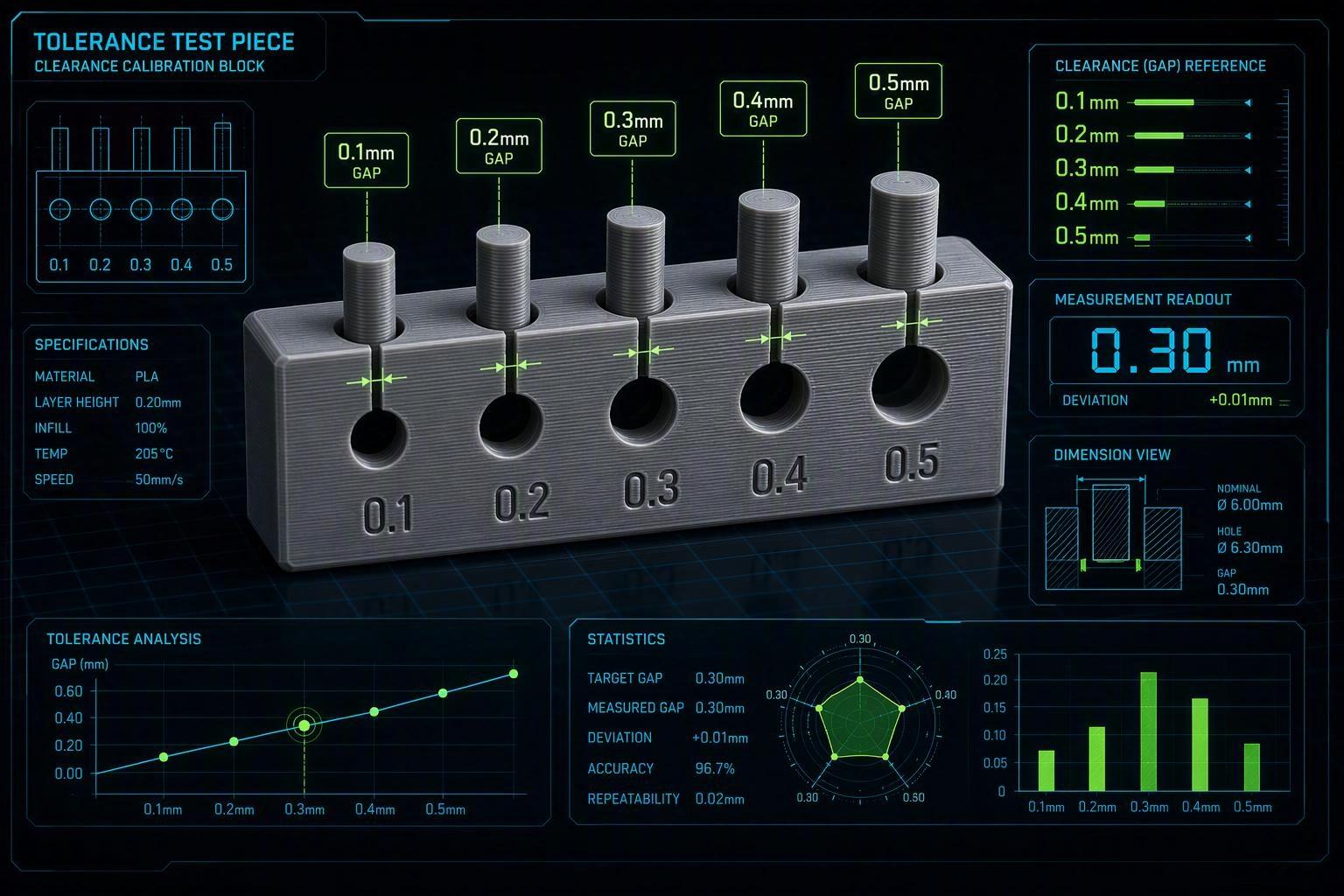
Record your baseline. The largest gap that still feels like a press fit is your press-fit clearance. The smallest gap that slides smoothly is your sliding-fit clearance. The gap just looser than that is your loose fit.
Apply it to your CAD. Subtract (or add) your measured clearances to the mating dimensions, then reprint just the test if you want to confirm before the real part.
Pro Tip: Write the working clearance values for each printer + material combo down. They stay valid for that combination until you change nozzle, layer height, flow, or material — so a one-line note now saves you from re-running the test later.
Troubleshooting Parts That Don't Fit
When something is off, work through the symptom instead of guess-punching the model around.
|
Symptom |
Likely causes |
Practical fixes |
|---|---|---|
|
Too tight |
CAD clearance too small; over-extrusion; elephant's foot; holes printed undersized |
Add clearance in CAD; tune flow rate; enable elephant's foot compensation; use XY hole compensation; chamfer the lead-in edge |
|
Too loose |
Clearance too large; under-extrusion; scale/units error on export-import |
Reduce modeled clearance; calibrate extrusion; confirm units and scale are consistent between parts |
|
Warped |
Poor bed adhesion; wrong bed temp; drafts/uneven cooling; large flat areas |
Clean the bed; use a brim or raft; bring bed temp into range; control cooling; use an enclosure for ASA |
|
Misaligned |
Warped mating faces; support residue on contact surfaces; scale mismatch; perpendicularity drift |
Flatten or reprint warped faces; clean/sand support marks; confirm matching scale; add alignment features (pins, keys) with realistic clearance |
A capture worth repeating: if only one feature is tight, change that dimension rather than rescaling the whole part. And when a gear mesh is too tight or too loose, the same clearance thinking applies to tooth backlash — covered in our gears design guide.
FAQ
Is 0.2 mm clearance enough for FDM 3D printing? Often yes, as a sliding-fit starting point on a well-calibrated machine — but test it on your printer and material before trusting it.
How much clearance should I add for a press fit in 3D printing? Start around 0.05–0.15 mm per side, then verify with a test couple. Press fits are sensitive to material shrinkage, so a small sample is worth the five minutes.
Why do my 3D printed holes come out too small? Internal circular features shrink because the slicer pulls filament inward as it traces the arc (arc compression). XY hole compensation, horizontal expansion, or slightly larger hole dimensions in CAD fixes it.
Does PETG need more clearance than PLA? Generally yes. PETG shrinks a little more than PLA, so plan slightly more clearance and check first-layer squish, which is stringier on PETG.
Why does my sliding fit only fail near the bottom? That's almost always elephant's foot — the first layers are squished wider than the rest. Enable compensation, or chamfer the base of the moving feature.
Conclusion: Fit Starts in the Slicing, Not Just the CAD
Getting parts to fit is less about memorizing magic numbers and more about knowing your printer's real tolerances. Design in clearance, account for the material's shrinkage, and handle the factors — nozzle, orientation, elephant's foot, flow, compensation, and layer height — that silently change your dimensions.
Practical takeaway: never trust a fit to a default number. Print a small tolerance test with your real settings, read your actual press, sliding, and loose baselines, and apply them to your model. That ten-minute step is what separates a part that binds on the bench from one that assembles first try. For more ways to keep functional FDM parts reliable, browse the rest of our engineering guides on the SOVOL blog.