




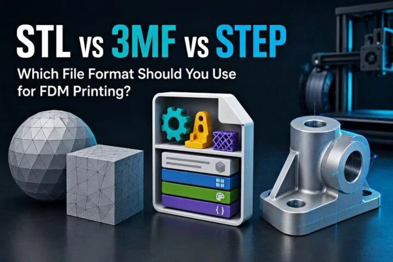
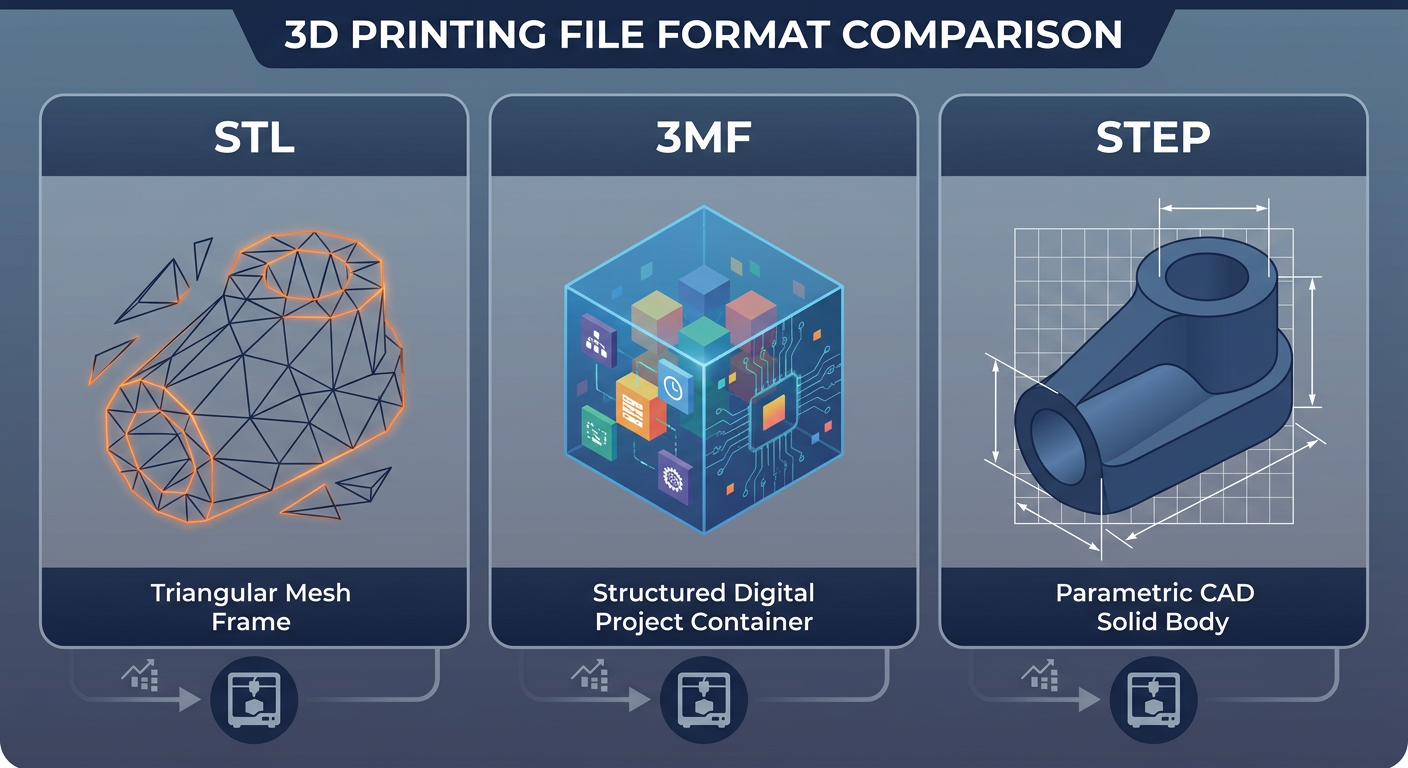
Understanding STL vs 3MF vs STEP helps you select the best file format for 3D printing based on whether you need simple mesh exchange, multi-color metadata, or exact parametric engineering data.
At a Glance: Comparison Table of 3D Printing File Formats
Before diving into the detailed mechanics, here is how these three 3D printing file formats compare across key workflow criteria:
|
Feature / Metric |
STL (.stl) |
3MF (.3mf) |
STEP (.step / .stp) |
|---|---|---|---|
|
Primary Data Type |
Triangulated Surface Mesh |
XML-based Mesh Archive Container |
Mathematical BREP / NURBS Solid |
|
Measurement Units |
Unitless (Slicer infers units) |
Defined unit scale, commonly millimeters |
Explicit (Embedded CAD units) |
|
Multi-Color & Material Data |
❌ No native support |
⚠️ Can store color and material data; support varies by slicer |
⚠️ CAD-dependent (Not standard for print) |
|
Slicer Project Settings |
❌ None (Geometry only) |
⚠️ Possible (Slicer-dependent archive) |
❌ None (Geometry only) |
|
Parametric CAD Editing |
❌ Extremely difficult (Mesh facets) |
❌ Extremely difficult (Mesh facets) |
✅ Native & seamless in parametric CAD |
|
Curved Surface Precision |
Polygon approximation (Tessellated) |
Polygon approximation (Tessellated) |
Exact mathematical curves (True radii) |
|
Slicer Compatibility |
Very broad compatibility |
Excellent (Most modern slicers) |
Depends on software & version (Modern slicers) |
Understanding the Big Three: What Are STL, 3MF, and STEP?
To choose the right format, you first need to understand how each file type stores geometric and manufacturing information.
STL (Stereolithography): The Legacy Mesh Standard
Introduced in 1987 for early stereolithography systems, the STL file is the oldest and most widely used format in additive manufacturing. An STL file represents a 3D object by covering its outer surface with a continuous mesh of tiny interlocking triangles (a process called tessellation).
Each triangle in an STL file is defined solely by three corner coordinates (vertices) and a directional vector pointing outward (the normal vector).
Key Advantages of STL:
- Universal Slicer Compatibility: Virtually 100% of 3D slicers, legacy host software, and online viewers can open STL files without plugins.
- Lightweight for Simple Geometry: Basic geometric shapes yield small file sizes that load quickly.
Key Limitations of STL:
- No Measurement Units: STL coordinates are raw numbers. The file does not specify whether those numbers represent millimeters, inches, or meters, leading to common unit scale errors.
- No Color, Material, or Assembly Data: STL cannot store multi-body relationships, color maps, or print orientations.
- Approximated Curves: Spheres, cylinders, and holes are flattened into polygonal facets, requiring millions of triangles to approximate smooth curves.
3MF (3D Manufacturing Format): The Modern Slicer Container
Developed by an industry consortium including Microsoft, Prusa, UltiMaker, and major CAD vendors, the 3MF file was designed specifically to fix the fundamental shortcomings of the aging STL format.
Technically, a 3MF file is an XML-based compressed ZIP archive. Rather than just containing raw triangle coordinates, a 3MF container holds the 3D mesh geometry alongside explicit measurement units, color assignments, material definitions, multi-object assembly hierarchies, and even complete slicer project settings.
Key Advantages of 3MF:
- Explicit Units: 3MF files define unit scale explicitly (defaulting to millimeters), reducing scaling errors across different software.
- Multi-Color and Multi-Material Ready: Stores distinct color maps and body assignments for multi-extruder or multi-material systems (like AMS or MMU).
- Full Project Sharing: Slicer project 3MFs save your model layout, custom painted supports, seam placements, infill densities, and printer profiles in a single shareable package.
- Watertight Mesh Validation: The 3MF specification enforces manifold geometry, reducing mesh corruption during export.
Key Limitations of 3MF:
- Still a Mesh Under the Hood: Like STL, 3MF stores surfaces as triangular meshes rather than editable parametric solids.
- Format Variations: A "Geometry 3MF" exported from CAD only carries shape and unit data, whereas a "Project 3MF" saved from a slicer carries toolpaths and settings that might not open seamlessly in a different slicer vendor's software.
STEP (Standard for the Exchange of Product Data): The Parametric CAD Benchmark
Standardized under ISO 10303, the STEP file (often saved as .step or .stp) is the universal standard for exchanging 3D solid geometry between professional CAD programs like Fusion 360, SolidWorks, FreeCAD, Onshape, and Inventor.
Unlike STL and 3MF, a STEP file does not use a mesh of flat triangles. Instead, it uses Boundary Representation (BREP) and NURBS (Non-Uniform Rational B-Splines) mathematics to define solid 3D geometry. A cylindrical hole in a STEP file is defined mathematically as a true cylinder with a precise radius and center axis—not as an approximation made of 32 or 64 flat polygon panels.
Key Advantages of STEP:
- True Mathematical Precision: Curves, arcs, and fillets maintain exact mathematical definitions regardless of file scale.
- Seamless CAD Editing: STEP files import cleanly into parametric CAD tools as editable solid bodies, allowing you to modify hole diameters, chamfers, or dimensions effortlessly.
- Preserved Assembly Structure: Multi-component engineering projects can retain individual parts and spatial layout depending on export settings and software compatibility.
Key Limitations of STEP:
- Not a Direct Print File: 3D printer hotends move along discrete paths; slicers must convert STEP solid geometry into a triangle mesh during import before calculating toolpaths.
- No Slicer Project Settings: STEP files do not carry slicer-specific print parameters like infill patterns, cooling overrides, or support paints.
STL vs 3MF vs STEP: Core Technical Differences Compared
Geometry Representation: Triangles vs. Mathematical Solids
The core difference between mesh formats (STL, 3MF) and CAD solid formats (STEP) lies in how surfaces are calculated:
- Mesh Tessellation (STL & 3MF) breaks curves into flat triangular panels. If you zoom in on a printed cylinder exported from a low-resolution STL, you will see visible flat facets. Increasing the triangle count smooths the curve, but it inflates the file size exponentially.
- BREP Geometry (STEP) stores mathematical equations for surfaces. When you import a STEP file into a modern slicer, the slicer generates an optimized mesh directly at import time, giving you maximum smoothness without bloating your CAD working files.
Unit Information and Scale Accuracy
One of the most frequent frustrations in FDM printing is importing a model and finding it microscopic (1/25.4th scale) or giant (25.4 times too large).
-
STLs are unitless. If a designer creates a part in Fusion 360 set to inches and exports an STL, the coordinates are saved as plain numbers (e.g.,
1.0). When imported into a slicer set to millimeters, the slicer interprets1.0as1.0 mminstead of25.4 mm. - 3MF and STEP files usually embed unit metadata. Slicers generally detect defined units automatically, though verifying scaling after import remains a good practice.
Multi-Part, Multi-Color, and Assembly Data
If you are printing multi-color models or complex multi-part projects:
- STL requires exporting every color or component as an individual STL file. You must then import them together into the slicer and hope their coordinate origins align automatically—or manually align them on the build plate.
- 3MF embeds all assembly components and color assignments inside a single file. Modern multi-color FDM setups read 3MF multi-body structures natively, keeping parts mapped to specific extruders or filament slots.
- STEP retains individual solid bodies from CAD. When imported into modern slicers, multi-body STEP files can often split into distinct sub-parts depending on the software, making it easier to assign different colors or infill settings to individual components.
Editability and CAD Modifications
If you plan to modify or remix a design:
- Editing an STL file in parametric CAD is notoriously difficult. CAD software must convert thousands of individual triangular mesh facets into solid surfaces, which often crashes software or creates uneditable geometry.
- Editing a STEP file in Fusion 360, SolidWorks, or FreeCAD treats the model as a native CAD solid. You can use standard tools to measure distances, extrude faces, add thread profiles, or adjust hole sizes in seconds.
Slicer Compatibility: What Actually Happens Upon Import?
A common misconception is that slicers calculate G-code directly from smooth STEP mathematical equations without creating triangles. In reality, modern slicers handle STEP files through internal tessellation engines:
When you drag a STEP file into slicers like OrcaSlicer, PrusaSlicer, or Bambu Studio, the slicer's internal engine (such as OpenCASCADE) automatically converts the STEP solid model into a high-density triangle mesh. As documented in the PrusaSlicer STEP import release, the slicing algorithms then operate on this converted mesh.
Some slicers, like OrcaSlicer, allow you to adjust linear and angular deflection parameters under OrcaSlicer import settings to control exactly how fine the generated mesh will be during import.
Which Format Should You Choose for Your 3D Printing Project?
To streamline your workflow, select the file format based on your specific project type:
|
Project Requirement |
Recommended Format |
Key Reason |
|---|---|---|
|
Simple decorative model |
STL or 3MF |
Universal compatibility & lightweight |
|
Multi-color or slicer project |
3MF |
Multi-material mapping & project metadata |
|
Editable mechanical CAD model |
STEP |
Exact parametric curves & native editing |
1. Decorative Models & Simple Single-Color Prints -> Choose STL or 3MF
For statues, miniatures, desktop organizers, or display models downloaded from Printables, Thingiverse, or MakerWorld, STL remains perfectly fine. However, if a 3MF option is available, choosing 3MF can help preserve correct scaling and orientation.
2. Multi-Color, Multi-Material, or Community Slicer Profiles -> Choose 3MF
When downloading pre-configured print profiles (with pre-painted colors, custom support blocks, or tuned layer heights), 3MF is a common choice. It helps ensure that color mappings and print parameters transfer intact to compatible slicers.
3. Functional Mechanical Parts, CAD Remixes, & Assemblies -> Choose STEP
If you are designing mechanical brackets, gears, enclosures, or functional replacement parts—or sharing models for others to modify—providing STEP files alongside mesh formats ensures seamless editing. STEP maintains precise hole geometry, accurate dimensional tolerances, and full parametric flexibility in CAD suites.
If your project involves assembling multiple printed parts with hardware, review our guide on multi-part 3D printer assembly to optimize joint tolerances and alignment pins.
How to Solve Common 3D Printing File Format Issues
Fix 1: Incorrect Model Scale (2540% or 25.4x Inch-to-MM Mismatch)
- Problem: You import an STL file, and the model appears micro-sized or massive.
-
Cause: The model was exported in inches, but your slicer assumes millimeters (
1 inch = 25.4 mm). - Solution: Scale the model by 2540% (if too small) or 3.937% (if too large) in your slicer transform panel. Switch to 3MF or STEP for future exports to reduce the risk of this issue.
Fix 2: Visible Facets and Low Mesh Resolution
- Problem: Curved surfaces on your print look blocky and polygonal.
- Cause: The STL file was exported with low mesh export tolerance.
- Solution: Re-export the model from your CAD software as a STEP file or a high-resolution 3MF file with refined chordal deviation / deflection settings.
Fix 3: Lost Colors or Disassembled Multi-Body Models
- Problem: A multi-color model imports as a single merged gray block or scatters into disconnected parts across the build plate.
- Cause: Exporting a multi-body design as a single STL strips object hierarchy.
- Solution: Export the assembly from your CAD software as a single 3MF file or STEP file. In your slicer, choose the option to import as a single object with multiple parts if supported.
Fix 4: Slicer Import Errors and Non-Manifold Meshes
- Problem: The slicer warns that the model contains non-manifold edges, inverted normals, or self-intersecting faces.
- Cause: Corrupted mesh geometry created during STL export.
- Solution: Use your slicer’s repair function or a dedicated mesh-repair tool to fix non-manifold geometry. The exact repair options vary by software. You can also export the design as a clean STEP file directly from CAD.
If you encounter print surface artifacts after resolving file import issues, check our detailed guide on slicer layer settings and surface quality to fine-tune seam alignment and perimeter flow.
Simple CAD-to-Print Workflow for FDM Printing
To keep your 3D printing workflow clean and error-free, follow this simple pipeline:
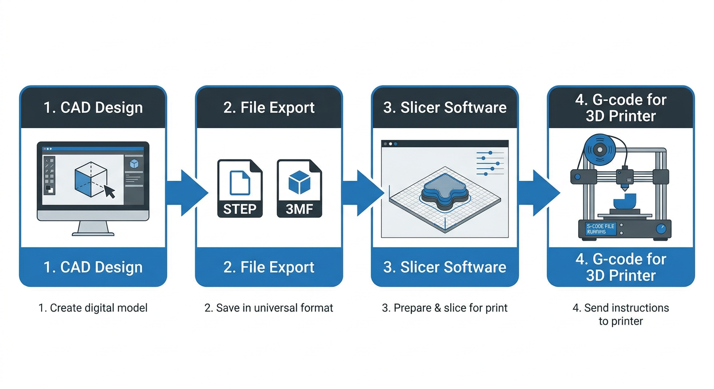
- Design in CAD: Create your parametric model in Fusion 360, SolidWorks, FreeCAD, or Onshape.
- Export the Primary File:
- For functional single/multi-part designs, export as a STEP (.step) file.
- For multi-color or texture-rich designs, export as a 3MF (.3mf) file.
- Import into Your Slicer: Drag the STEP or 3MF file into your slicer (OrcaSlicer, PrusaSlicer, Bambu Studio, or Cura).
- Verify Scale and Orientation: Check that the build plate orientation minimizes supports and respects mechanical stress lines.
- Slice & Print: Slice the model and send the G-code to your FDM 3D printer.
For broader troubleshooting during printing, consult our comprehensive guide on FDM 3D printing troubleshooting to solve extrusion, bed adhesion, and mechanical tuning challenges.
Frequently Asked Questions (FAQ)
FAQ 1: Does printing a STEP file directly improve 3D print quality over a high-res STL or 3MF?
Not automatically. Because slicers convert STEP files into a triangle mesh during import, a high-resolution 3MF or STL exported with fine tolerances can produce an identical toolpath. However, importing a STEP file delegates mesh creation to the slicer's internal engine, which may reduce manual mesh-export adjustments.
FAQ 2: What is the difference between a 3MF Project File and a 3MF Geometry File?
A Geometry 3MF contains only the 3D model mesh, units, and color/material assignments (used for sharing 3D models). A Project 3MF is saved from inside a slicer and contains the model mesh plus printer profiles, filament settings, layer height modifiers, painted support blocks, and build plate arrangements.
FAQ 3: Why can't I edit an STL file easily in CAD software like Fusion 360?
STL files consist of thousands of flat surface triangles without underlying mathematical parametric rules. When imported into parametric CAD tools, the software must process each triangle as a separate surface facet, making it difficult to select cylinder centers, measure exact distances, or adjust wall thicknesses.
FAQ 4: Do all 3D slicers support STEP file import?
Many current slicers, including OrcaSlicer and PrusaSlicer, support STEP import, but compatibility and import options vary by slicer and version. Check your slicer’s documentation before relying on STEP files.
Final Verdict: Choosing the Right Format for a Smooth FDM Workflow
There is no single "best" file format for every situation, but modern FDM printing has clearly moved beyond legacy STLs:
- Keep STL for simple community downloads and legacy compatibility.
- Adopt 3MF for multi-color printing, sharing complete slicer projects, and reducing scaling errors.
- Standardize on STEP for mechanical designs, functional CAD projects, and sharing editable models with the maker community.
By matching the right file format to your project requirements, you can reduce the chance of scaling mistakes, preserve crisp geometry, and ensure smooth printing on your FDM setup.