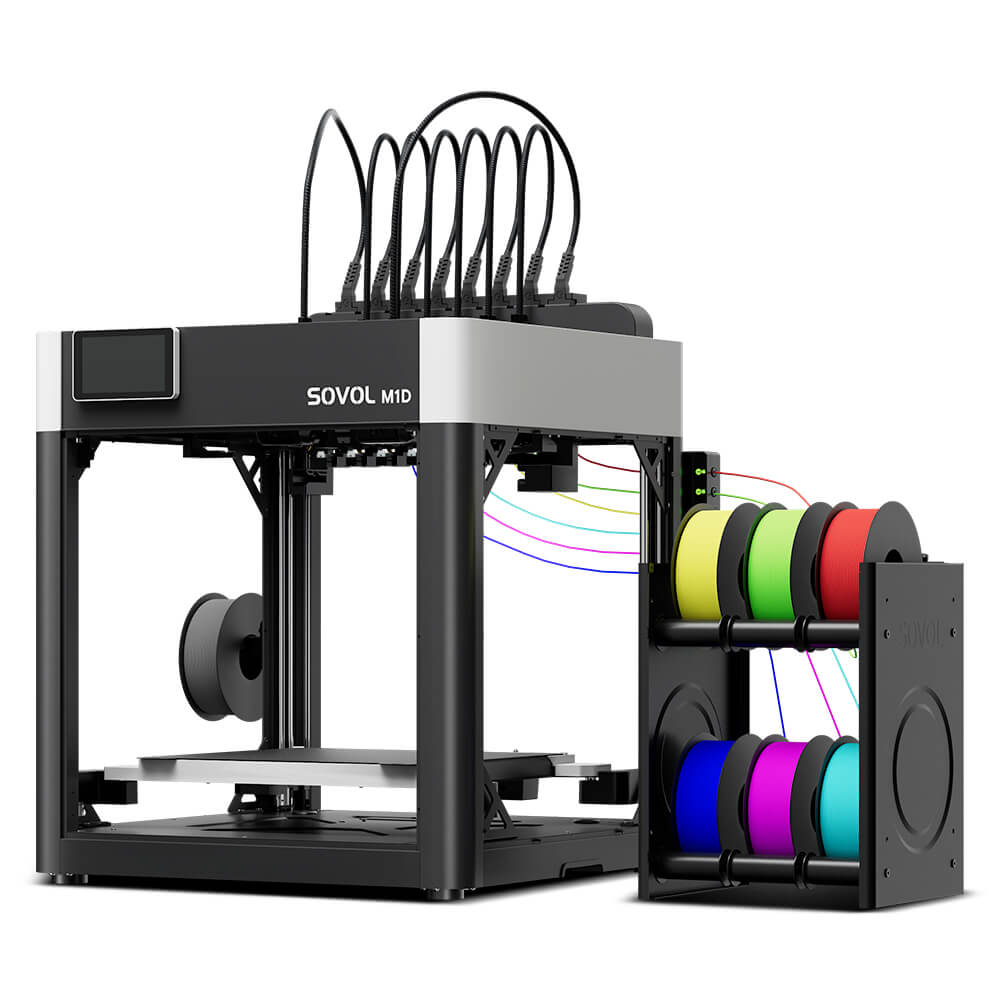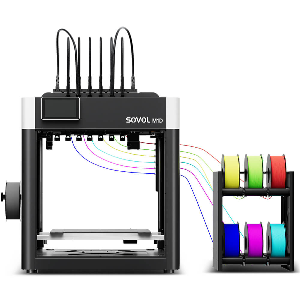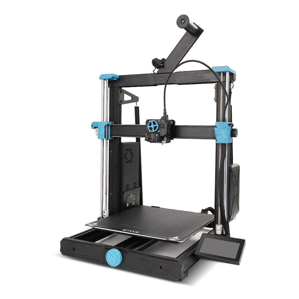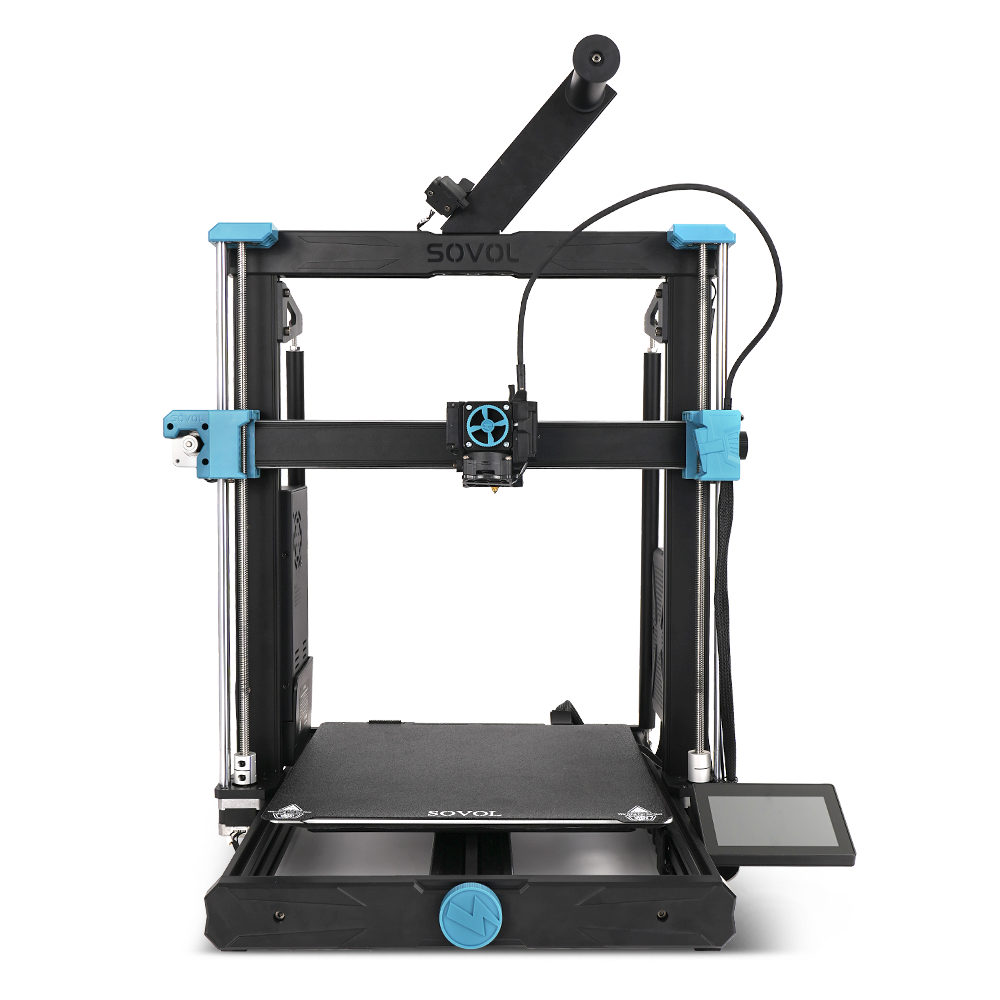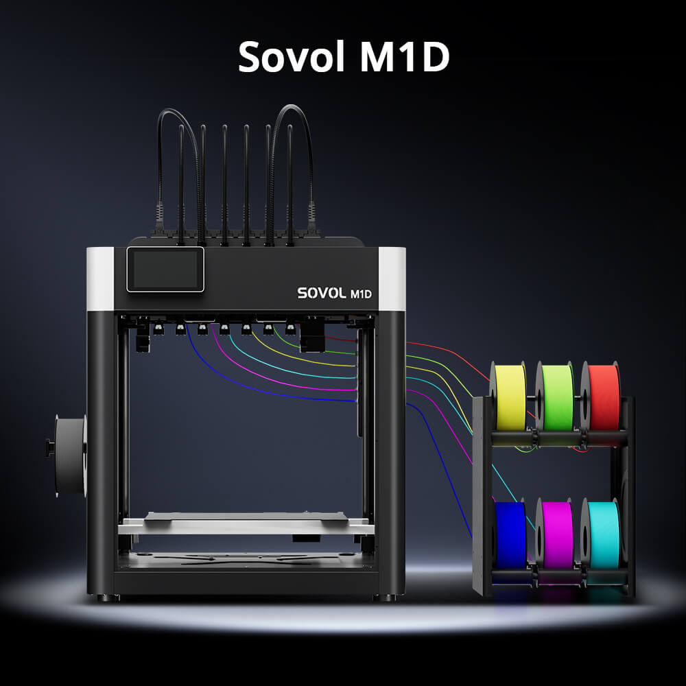





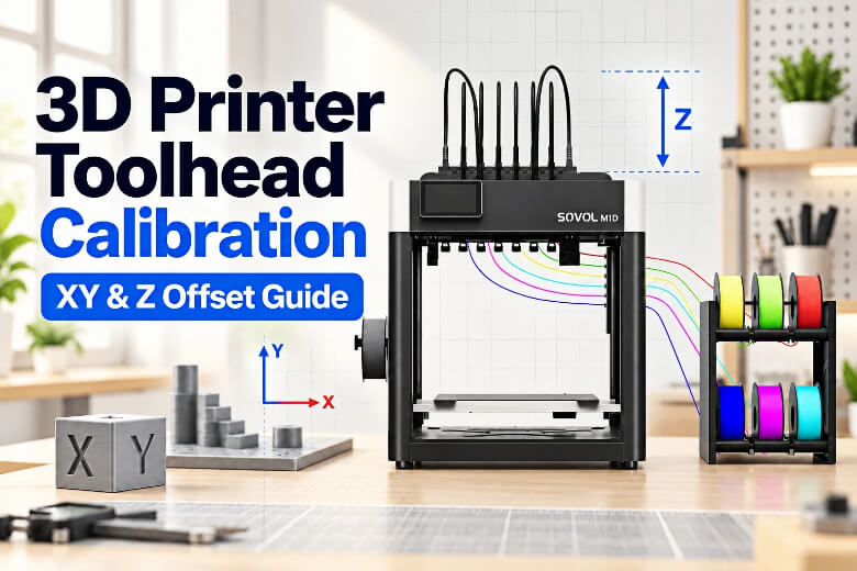
Traditional IDEX printers usually use two independent toolheads, while the Sovol M1D uses a DualX 1+6 tool-changing architecture: one fixed toolhead plus six switchable ones, supporting up to seven colors or materials. The calibration principles are related, but the available modes and calibration workflow may differ, so this guide separates the shared concepts from the machine-specific steps.
By the end of this article you will be able to tell XY offset, Z offset, extrusion alignment, and nozzle-height consistency apart, recognize which one is wrong from the print itself, and run a calibration workflow that matches the machine in front of you.
Key Takeaways:
- XY offset and Z offset are separate error classes: XY decides where a tool deposits material horizontally, Z decides at what height, and a horizontal shift generally requires checking XY alignment rather than changing the Z value.
- Nozzle-height consistency is a nozzle-to-nozzle measurement, distinct from the nozzle-to-plate Z offset that a probe calibration produces.
- Offset values are valid only for the mechanical state they were measured in, so a change to the motion system, hotend position, or probe location invalidates them.
- Automatic calibration reduces guesswork but does not replace a first-layer check, and the reference tool is the first thing to inspect when one tool keeps failing.
Why 3D Printer Toolhead Calibration Matters on a Dual-Toolhead Machine
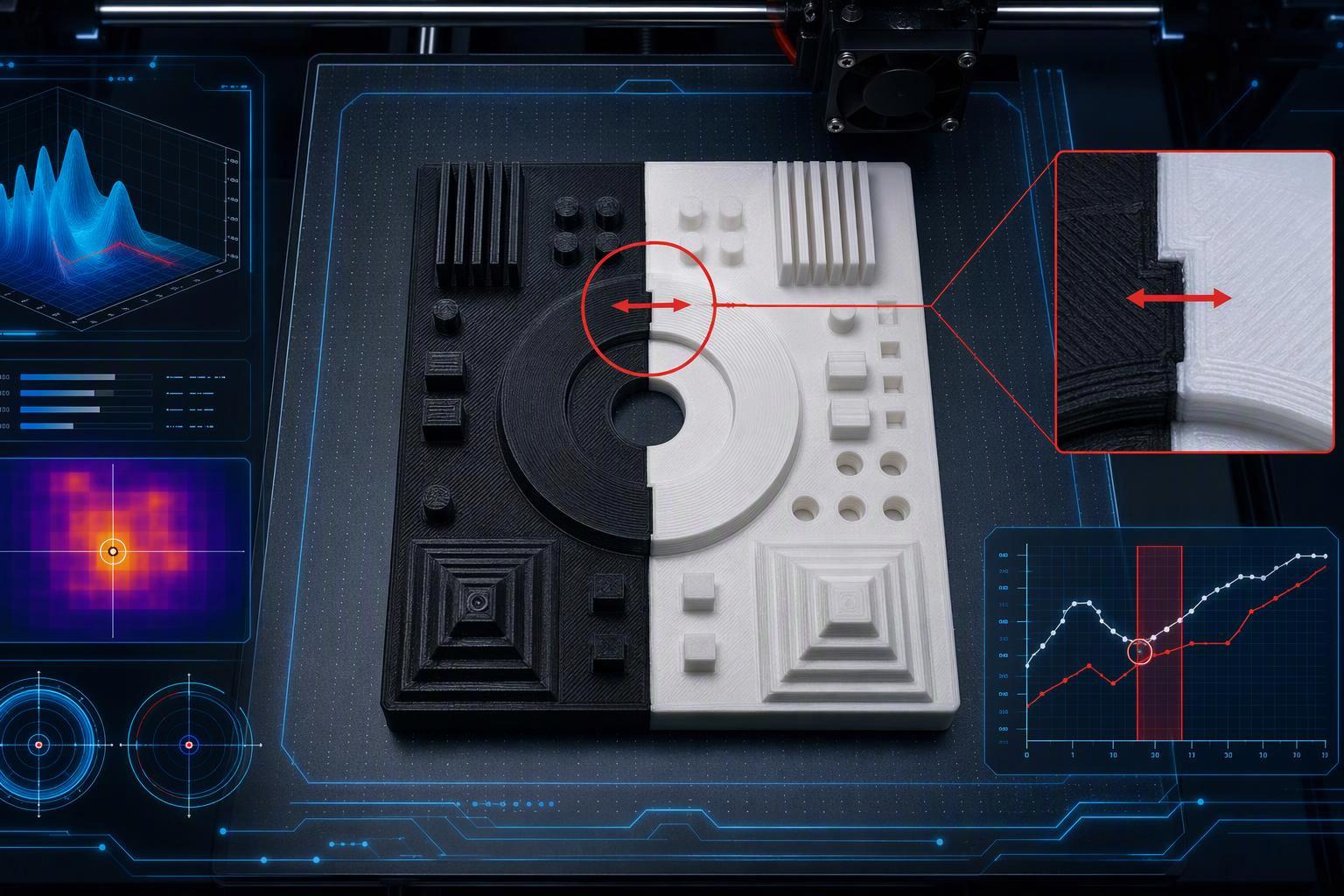
A dual-toolhead machine can make small alignment errors more visible, so an error that a single-nozzle printer quietly absorbs shows up on the first layer. On one nozzle, a small height error just squishes the plastic a little more. On two, the second tool has to land in the same place the first one did, and any offset between them shows up as a visible step.
The parameters are stored, not guessed. Copy and Mirror raise the stakes further, because Klipper's g-code reference documents the copy and mirror carriage modes as firmware motion relationships between two carriages rather than slicer conveniences (Klipper G-Codes reference, retrieved 2026).
Pro Tip On a multi-toolhead machine the alignment error a single-nozzle printer absorbs becomes visible. Treat every offset value as valid only for the mechanical state it was measured in.
XY Offset, Z Offset, Extrusion Alignment, and Nozzle-Height Consistency: What Each One Actually Controls

XY offset calibration on a 3D printer sets where a tool deposits material in the horizontal plane, while Z offset calibration sets the height at which it deposits it, and the two are different error classes rather than two versions of the same number. Klipper's configuration reference defines the probe offsets relative to the nozzle, describing x offset and y offset as the distance in mm between the probe and the nozzle along each axis, with a default of 0 (Klipper configuration reference, retrieved 2026). That is the probe-to-nozzle relationship, which is a separate parameter from the nozzle-to-nozzle tool offset you adjust when two tools disagree.
In probe-based calibration workflows, Z offset describes the relationship between the probe trigger point and the nozzle-to-bed position, not a property of the bed. Klipper's probe calibration documentation defines the value as the nozzle-to-bed distance at probe trigger and saves the result with SAVE_CONFIG (Klipper probe calibration, retrieved 2026). The exact meaning and adjustment method can vary by firmware and printer design. Nozzle-height consistency is the third, easily confused parameter: it compares one nozzle to another rather than a nozzle to the plate. Bambu Lab's H2D documentation performs nozzle offset calibration against a sensor behind the heatbed, and documents a second high-precision routine that scans a printed pattern on the XY plane (Bambu Lab H2D FAQ, 2025-03-25).
Extrusion alignment is per toolhead and per machine. Klipper's rotation-distance documentation explains why flow calibration is per machine and per spool: the value depends on the grip of the hobbed bolt, varies from printer to printer, and can even change between filament spools (Klipper rotation distance, retrieved 2026). Slicers expose these as profile settings rather than universal numbers; OrcaSlicer's wiki documents a dedicated IDEX/IQEX configuration page and per-extruder basic information and retraction settings (OrcaSlicer wiki, retrieved 2026).
|
Parameter |
What it controls |
What a wrong value looks like |
|---|---|---|
|
XY offset |
Where a tool deposits material horizontally |
One color shifted left/right or front/back at the boundary |
|
Z offset (nozzle to plate) |
Height at which the nozzle meets the plate |
First layer too squished or not touching, across the whole bed |
|
Nozzle-height consistency |
One nozzle's height relative to the other |
One copy or one color under-squished while the other is fine |
|
Extrusion / flow per toolhead |
How much filament each tool pushes |
One color over- or under-extruded while the other looks correct |
What Goes Wrong When Calibration Is Off: Interfaces, First Layers, Supports, Text, and Copy or Mirror Modes

IDEX printer calibration errors show up first at the interfaces between two tools, which is why the same model can print perfectly in dual-material mode and fail in Copy Mode. Copy Mode is unforgiving because both toolheads move in sync at a fixed offset, and Mirror Mode can be the tighter envelope of the two: either one may hold a perfect first layer on one side while the other side does not (Sovol Copy vs Mirror comparison, 2026-06-24).
Dual extrusion alignment problems are not limited to color boundaries. A nozzle that sits slightly lower than its partner can drag through fresh lines the other nozzle just laid, and an idle nozzle that oozes can build up blobs that eventually become a collision. Supports and text are the harshest tests because both depend on a tool change landing in exactly the right place: a support interface printed by the wrong tool at the wrong height either fuses to the model or fails to hold it.
The shared cause is that offset values are conditional. Klipper states that a change to the printer's motion system, hotend position, or probe location will invalidate the results of PROBE_CALIBRATE (Klipper probe calibration, retrieved 2026). Prusa's XL multi-tool manual calibration prints an X/Y comb pattern you read by eye, and requires a second print after adjustment to confirm the new offsets (Prusa multi-tool manual calibration, 2026-05-10). Both procedures assume the machine is in the same mechanical state it was measured in.
How to Recognize a Misaligned Toolhead, What to Check First, and a Safe Calibration Workflow
How to align two toolheads starts with reading the defect, not with opening a settings menu, because the direction of the error tells you which parameter to touch. A wrong X offset shows as a left or right shift at the color boundary, and a wrong Y offset as a front or back shift; a gap between the two colors means one direction of correction, an overlap ridge means the other (Sovol IDEX calibration guide, 2026-09-29). Inspect the test from all sides before you change anything, and settle Z before XY, because XY values mean little until both nozzles share an effective Z height.
Then check the hardware before the numbers. Prusa's multi-tool selftest guidance states that all tools are adjusted based on the first tool, so a problem with tools 2 through 5 may actually be a problem with tool 1's calibration (Prusa multi-tool selftest guidance, retrieved 2026). The same guidance requires the outside of the nozzle to be clean before tool offset calibration and instructs users to unload any loaded filament before starting. Residue on the nozzle or the rails corrupts the measurement itself, so cleaning is part of the calibration, not preparation for it.
A safe workflow follows the order the manufacturers document. Snapmaker's Artisan documentation splits the workflow into bed leveling, Z offset, and XY offset, with the XY step printing a pattern the user inspects (Snapmaker Artisan calibration, 2022-12-06). Prusa's XL procedure reads the most-aligned mark per comb and applies the measured value to that tool's offset, with offsets stated relative to Tool 1 (Prusa multi-tool manual calibration, 2026-05-10). Check toolhead and material assignments, color transitions, and tool-change points in the sliced preview before you print, then reprint the test rather than trusting the first result.
How Automatic Calibration Helps, Where Its Limits Are, and When to Recalibrate
Automatic calibration removes the guesswork from measurement but does not remove the need to verify the result on a first layer. Bambu Lab's own FAQ notes that its visual XY calibration cannot cover the Z direction, and that the Z component is carried by the ordinary eddy-current calibration instead (Bambu Lab H2D FAQ, 2025-03-25). That division of labor is the honest limit of a camera-based method: it measures what it can see on the plane, and something else has to handle height. For the most automated machines, no primary source publishes a measured accuracy or repeatability figure, so treat any specific tolerance you see quoted as unverified.
Recalibrate on triggers, not on a schedule. Prusa's out-of-bounds article adds vibration as a false-failure cause, noting that a printer running next to the machine can propagate vibration and cause a tool offset calibration to fail (Prusa tool offset out of bounds, retrieved 2026). If one toolhead consistently prints worse than the others, tune its flow rate, retraction, and print speed individually before assuming a hardware fault.
How we apply this at SOVOL, the publisher of this guide. Our M1D combines automatic vision calibration with Auto Z-Lift and Z-Offset Compensation to assist with toolhead alignment. A dedicated rear camera calibrates XY offsets across the toolhead system, while two toolhead-mounted cameras independently calibrate the extrusion accuracy of the nozzles, and Auto Z-Lift and Z-Offset Compensation help compensate for Z-height differences between toolheads. Even so, automatic calibration does not replace print verification: users should still inspect the first layer and the test print, because the result is only as good as the mechanical state it was measured in.
Frequently Asked Questions
What is XY offset calibration on a 3D printer?
It is the step that tells the firmware where each toolhead's nozzle actually sits in the horizontal plane, so two nozzles that should land on the same point do. Marlin's M218 command stores a hotend's XY offset as its own parameter, kept separate from the probe's Z offset (Marlin M218 documentation, retrieved 2026). Treat it as a positional correction, not a print-quality setting.
What does Z offset calibration control?
In probe-based calibration workflows, Z offset describes the relationship between the probe trigger point and the nozzle-to-bed position. Klipper's probe calibration page defines z offset as the gap between nozzle and bed when the probe reports a trigger (Klipper probe calibration, retrieved 2026), but the exact meaning and adjustment method can vary by firmware and printer design. Get it wrong and the first layer is either squashed into the plate or floating above it.
How do I know if two toolheads are aligned?
Print a small two-tool test and measure the offset between the two sets of lines, rather than judging by eye on a finished model. Bambu Lab's H2D workflow checks nozzle alignment by having the toolheads touch a sensor mounted behind the heatbed (Bambu Lab H2D manual, 2025-04-22). A visible step at a color boundary is the same error, just measured on a print instead of a sensor.
Can automatic calibration fix every dual-toolhead problem?
No. Vendor documentation is explicit that it covers some error classes and not others. Mechanical faults, a partially clogged nozzle, or a loose toolhead mount also sit outside what a camera or probe routine can correct, so a first-layer check still belongs in the workflow.
How often should I calibrate a multi-toolhead printer?
After any change that moves the geometry: a toolhead swap, a collision, a failed tool change, or relocating the machine. Klipper states that altering the motion system, hotend position, or probe location invalidates the stored calibration result (Klipper probe calibration, retrieved 2026). Between those events, recalibrate when first layers or nozzle alignment stop being repeatable. The exact interval is machine-specific, so follow your manufacturer's schedule rather than a fixed number of prints.
Conclusion
Toolhead calibration comes down to naming the error before you touch a number. XY offset and Z offset are different error classes, nozzle-height consistency is a nozzle-to-nozzle measurement rather than a nozzle-to-plate one, and extrusion alignment is a per-toolhead value that changes with the machine and even with the spool. And because every offset is measured against a specific mechanical state, any change to the motion system, hotend position, or probe location invalidates the stored result.
That is why the workflow matters more than any single number. Read the defect, check seating and cleanliness first, settle Z before XY, reprint the test to confirm, and recalibrate on triggers rather than on a schedule.
Your next step is a single test print you inspect from all sides, with the sliced preview checked for toolhead assignments and tool-change points before you start. If you want to go further, the natural follow-ups are how multi-material printing changes support and interface design, how IDEX carriage geometry limits what fits on the bed, and what a first-print setup checklist should contain.