




You've probably had this happen: a bracket, a jig, or a phone stand that printed perfectly on your single-nozzle machine comes off a dual-toolhead printer with a smeared first layer, a weak seam where the two materials meet, or a support structure fused to the part. Nothing about the model changed. What changed is the machine.
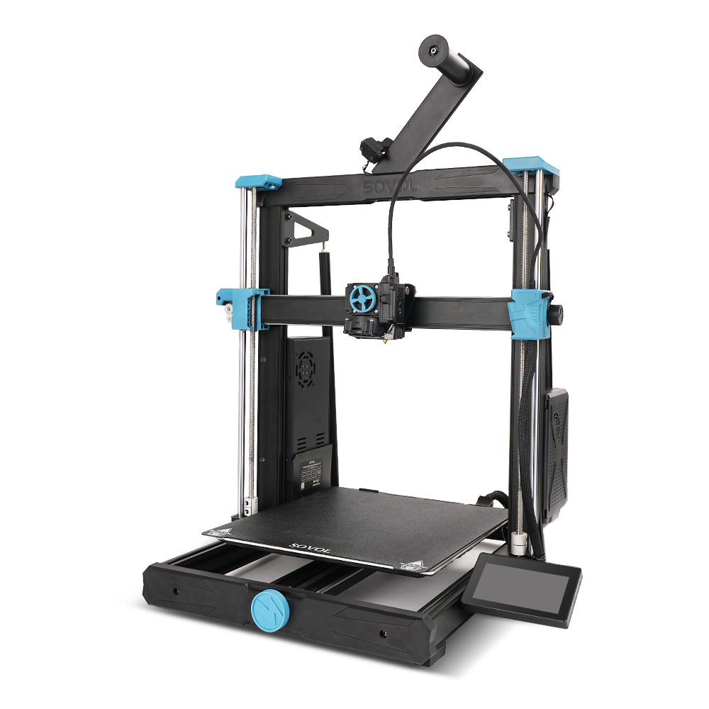
IDEX 3D printing design is the practice of preparing a model for a printer with two independent toolheads: two hotends, each on its own carriage with its own X motor, sharing one Y motor, so any movement along Y has to match for both heads at all times (MatterHackers, 2021-03-23). Toolhead assignment is the slicer step that decides which of those two heads prints which region of your part. Neither of those decisions exists on a single-toolhead machine, and both of them can turn a good model into a bad print.
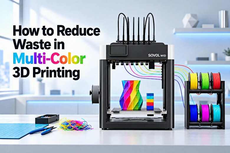
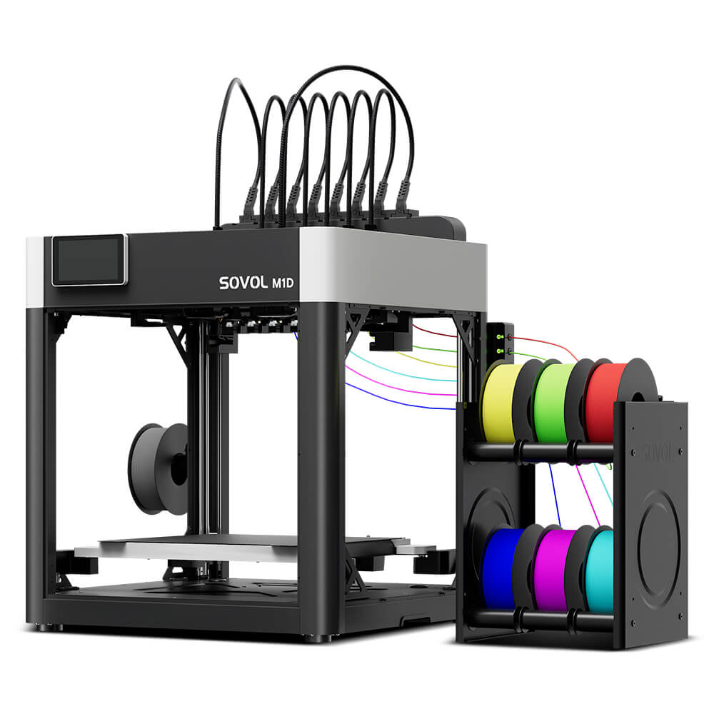
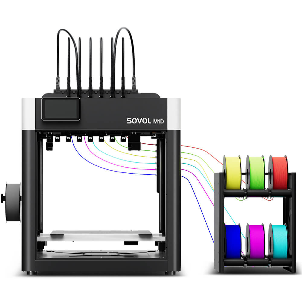
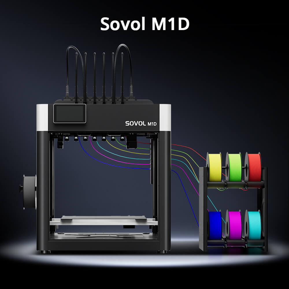
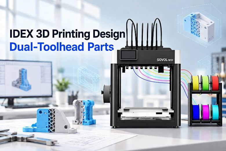
Traditional IDEX printers usually use two independent toolheads, while Sovol M1D uses a DualX 1+6 tool-changing architecture: one fixed toolhead plus six changeable toolheads, for up to seven colors or materials (Sovol M1D product page, 2026). The design principles in this guide apply to both systems, but the available printing modes and toolhead workflow may differ.
The goal here is a part that prints cleanly on a dual-toolhead machine: material regions assigned deliberately, interfaces that hold, and a tool-change pattern you have actually previewed rather than assumed. The steps below cover the design habits that carry over from standard FDM and the ones that do not.
Why IDEX 3D printing design needs more than single-toolhead habits

The core reason is mechanical: your two heads share one Y axis, so the geometry you can print is bounded by both carriages, not one. MatterHackers explains the two heads share Y motion, so Y moves must match, which is why IDEX machines cannot simply treat each head as an independent printer (MatterHackers, 2021-03-23). A part that fits a single-nozzle bed can still be too wide, too tall, or too close to a parked head.
The second difference is that a parked toolhead is not an inert one. MatterHackers frames the parked position as a benefit: the inactive head sits off to the side, though ooze control still needs settings, since a nozzle held at print temperature will drip (MatterHackers, 2021-03-23). Vision Miner's IDEX documentation recommends lowering the idle temperature of the waiting toolhead by roughly 100 °C below its print temperature for high-temperature materials, precisely because those drips land on the part when the head is picked back up (Vision Miner, retrieved 2026).
Key Takeaway: A design that ignores toolhead access, material regions, or interface geometry still slices and still prints. It just prints badly, and the slicer may not identify every design or assignment problem automatically.
What are the core design principles for a dual-toolhead part?
Five principles cover most of the design work, and each one maps to a setting you can point at in the slicer.
- Assign every material region to a toolhead. PrusaSlicer assigns a tool per part by double-clicking the colored rectangle in the object list, pressing a number key, or right-clicking the part in the 3D view and choosing Change extruder (Prusa Knowledge Base, 2026-05-10). A part left at the default follows the object, which is how the wrong head ends up printing your support.
- Keep the tool-change count low by design, not by hope. PrusaSlicer lets you send support and skirt to the current extruder specifically to minimize tool changes (Prusa Knowledge Base, 2026-05-10).
- Give each region enough volume to survive slicing. Regions thinner than a couple of extrusion widths are where assignment gets unreliable, and the threshold depends on nozzle diameter and layer height rather than a fixed number.
- Design the interface, not just the boundary. A simple butt joint may provide less mechanical security than an interlocking interface, depending on the materials and print conditions.
- Plan for the purge structure. Tool changes require priming, and that cost scales with the number of changes rather than the size of your part.
These are the IDEX printing tips that matter most: the design decisions that reduce tool changes are the same ones that reduce failure modes.
Which IDEX workflow fits my part?
Pick the mode before you pick the orientation, because each mode changes how much bed you actually get.
|
Mode |
Design approach |
Build volume |
Main design consideration |
|---|---|---|---|
|
Single Toolhead |
One material, one head |
300 × 300 × 350 mm |
Full bed width; no interface to design |
|
7-Toolhead Printing |
Multi-color or multi-material in one part, regions assigned per part or per feature |
240 × 300 × 350 mm |
Interface quality and tool-change count |
|
Copy |
Two identical parts, one per head |
178 × 300 × 350 mm × 2 |
Each part gets a reduced width |
|
Mirror |
A part and its inverse |
138 × 300 × 350 mm × 2 |
Tightest width of the four modes |
Dimensions above match the published specifications for the Sovol M1D; your own machine's numbers may differ. Mirror mode prints a part and its inverse, so whether two different models can be printed simultaneously depends on the printer's supported modes and slicer workflow (Raise3D Academy, undated).
Soluble support is the other workflow decision, and it comes with storage rules. Prusa's soluble-support guidance notes PVA and BVOH stick to PLA and PETG but not to PEI sheets, and that both are strongly hygroscopic, so deteriorated filament causes loading and clogging problems (Prusa Knowledge Base, 2026-05-10). If your part needs internal supports you cannot reach, that is the workflow to choose.
How does model orientation affect toolhead access, support placement and collision risk?
Orientation decides whether the second head can physically reach its regions without the first head in the way, and it decides where supports land.
Rat Rig treats the two toolheads as separate motion systems: print mode is selected by macro, XY offsets are calibrated per tool, and the commissioning guide advises running a nozzle-alignment calibration before each multi-material print because temperature, nozzle type, or chamber conditions can shift those offsets (Rat Rig, 2026-03-09). Vision Miner specifies both nozzles within a tolerance of 50 microns and 5 mm of retraction when a toolhead parks (Vision Miner, retrieved 2026). Neither figure is a clearance rule you can design to; they are alignment targets you have to maintain.
There is no universal clearance figure that applies across machines. Clearance depends on nozzle diameter, layer height, material, calibration state, and the specific geometry of the parked head, and no source publishes a single number that covers those variables. Design tall features away from the parked position, and verify the rest in the preview.
Depth stays at 300 mm and height at 350 mm across all four.
How should I structure material regions and interfaces in CAD?
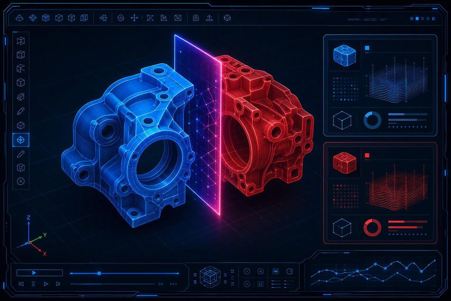
Model each material region as a separate body, then use Split to parts rather than Split to objects. Prusa's documentation explains that Split to parts keeps the components in their relative positions even when they float above the bed, which is exactly what a multi-material assembly needs, while Split to objects places each shell separately on the plate (Prusa Knowledge Base, 2026-05-10).
Interface strength is where the design decisions pay off, and the evidence points one way: the specific material pair determines the bond, not the similarity of print temperatures. A 2026 multi-material adhesion study found that swapping the support material changed measured adhesion by more than three times for the same base polymer, which is why "they print at similar temperatures" is not a compatibility argument (PMC, 2026-03-26).
Interface geometry is a separate lever from material choice. A peer-reviewed study on interfacial mechanical design found that interlocking geometries substantially raised crack propagation energy over flat butt joints (Nature portfolio, 2026). Those figures are crack-propagation energy, not tensile strength, and they come from one test geometry rather than a general guarantee. Smaller layer heights tend to deepen that interlock, which is one reason the same pair can behave very differently at 0.1 mm and 0.3 mm layers.
How do I reduce tool changes and verify toolhead assignments in the slicer?
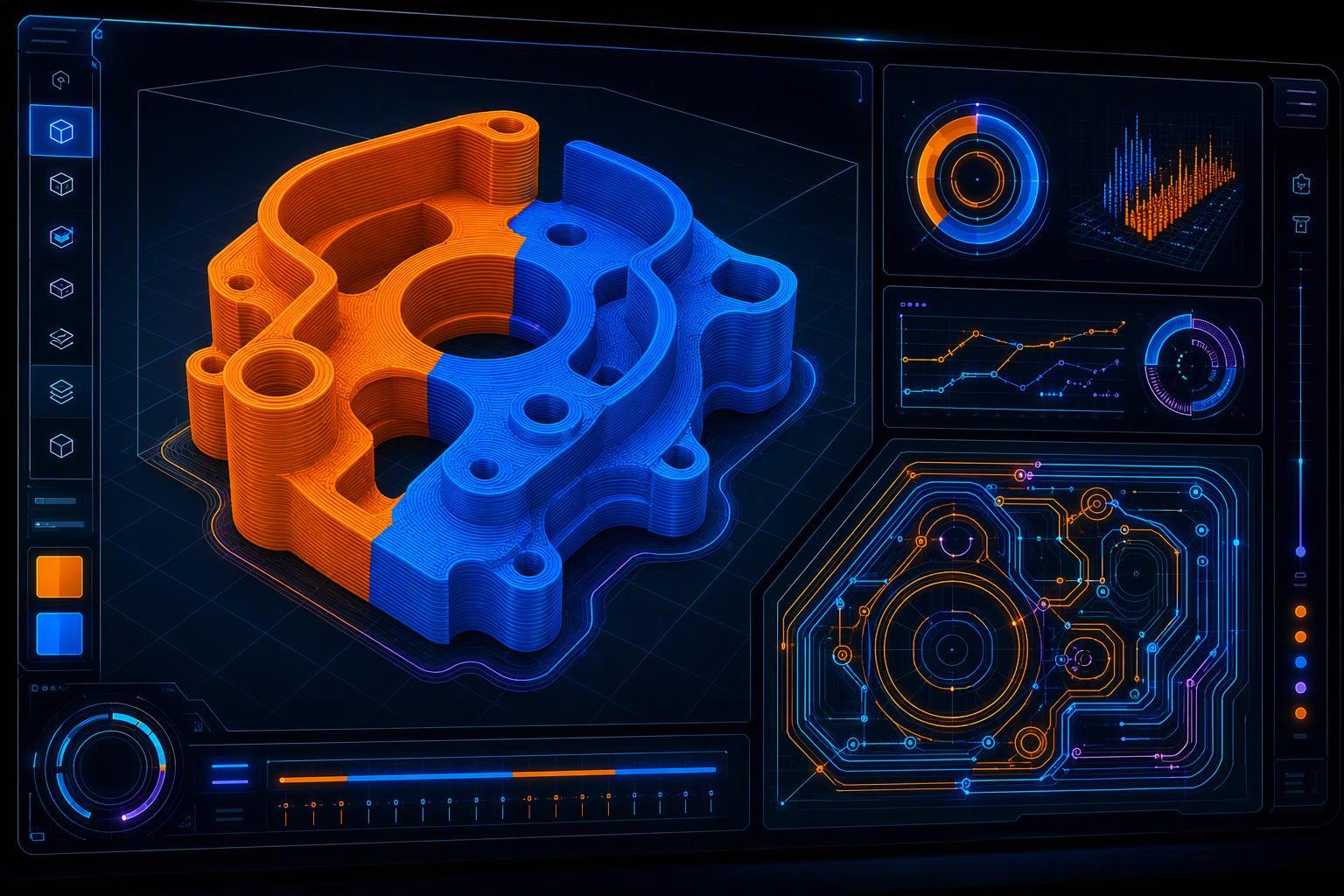
Slice the part, then read the preview before you commit filament. Prusa's wipe-tower documentation notes that the tower scales with the number of tool changes rather than the size of the object, and that it is rarely solid because sparse and dense infill is adjusted each layer to waste as little filament as possible (Prusa Knowledge Base, 2026-05-10). A design that forces a change every layer pays for it in tower volume, not in part volume.
A vendor benchmark gives a sense of scale: removing some wipe-tower layers cut total print time by a little over 3% and tower filament use by more than 16% across Prusa's own multi-material projects (Prusa Knowledge Base, 2026-05-10). It's a vendor-run test, not a third-party measurement, but the direction is clear.
Verification is a two-step check. First, use the tool color scheme in the preview and drag the layer slider: a tool change in a place you did not design for means an object, part, or modifier still has the wrong extruder assigned. Second, slice a small test object with the same settings before the real print, which costs minutes and shows tool-change quality, oozing, and alignment on something you can throw away (Vision Miner, retrieved 2026).
How we apply this at SOVOL, the publisher of this guide. On the M1D, the fixed toolhead can stay dedicated to support material or the most-used color, while the changeable heads handle the rest. It does not assign tools for you: you still set every part and modifier in the slicer and read the preview yourself.
What commonly goes wrong, and how do I fix it before committing to the full print?
The most common failure is a part that sliced without errors and printed with the wrong head on a region. An incorrect or missing tool assignment can cause the wrong toolhead to print a region, and the fix is in the object list rather than in CAD. Modeling a boundary is not the same as assigning it.
The second is a weak interface between two materials that seemed compatible. The measured data backs the caution: for the same base polymer, a dedicated support material and a "close enough" alternative landed at opposite ends of the adhesion scale, so "use the matching support material" is not reliable advice (PMC, 2026-03-26).
The third is rigid filament printed over a soft material. Prusa's multi-tool guidance warns that when printing rigid filaments on top of TPE or TPU, the lower soft layers can be dragged around by the rigid filament on top of them, counteracted by increasing the minimal purge on the wipe tower (Prusa Knowledge Base, 2026-05-10).
Tip: Always verify tool assignments and material interfaces with a small test print before starting a long multi-material job.
Frequently Asked Questions
Can I use different materials on an IDEX 3D printer?
Yes, but compatibility is a property of the specific pair, not of the machine. Sovol's filament guide is blunt about it: "No pairing is universally compatible. Every combination above is a starting point to test, not a specification to trust" (Sovol, How to Choose Compatible Filaments for Multi-Material Printing, 2026). The same guide flags PLA with PETG as exhibiting poor adhesion, and rules out PLA with ABS on one plate because the two need bed temperatures far enough apart that no single setting serves both.
Should each material be designed as a separate body?
Yes. Keeping each material as its own body in the model gives the slicer something explicit to assign, and it keeps the interface between them a deliberate piece of geometry rather than an accident of where a boundary happened to fall. Merging everything into one solid removes that control. The assignment itself still happens in the slicer, not in CAD.
How can I reduce toolhead changes?
Group geometry by material so each head finishes a region before the other takes over, and keep the two regions from interleaving layer by layer. Fewer, larger tool changes cost less time and less purge than many small ones. Where a design calls for repeated identical parts rather than two materials, Copy or mirror modes sidestep the question by producing two parts per cycle.
Why do material interfaces fail?
Usually because the pair was assumed compatible rather than tested. Adhesion between two polymers depends on how they bond at the boundary, and that varies by combination in ways temperature similarity does not predict. Print a small interface test with the exact pair and settings before committing a full part, and treat any published compatibility chart as a shortlist, not a verdict.
Is IDEX suitable for small-batch production?
It can be, when the parts repeat and the material count stays low. Copy and mirror modes let one machine produce two parts per cycle without a second toolhead change, which suits short runs of identical geometry. The limits are the ones already covered: build volume shrinks in those modes, and any multi-material part still depends on a tested interface.
What is dual extrusion design?
It is the practice of preparing a model for tool-based printing where each head prints a defined region of the same part. The work covers toolhead access, material region assignment, interface geometry, and the tool-change pattern. A model that ignores those things will slice cleanly and print poorly.
Conclusion
Designing for IDEX comes down to four decisions that standard FDM never asks you to make: which head prints which region, how much bed each mode actually leaves you, how the interface between materials is shaped, and how many tool changes your geometry forces. Get those right and the part prints the way it did on your single-nozzle machine, with the added capability you bought the printer for.
The verification habit matters as much as the design habit. Preview the tool changes, confirm the assignment on every part and modifier, and run a small test before committing to a long print. Most IDEX failures are assignment failures rather than geometry failures, and assignment failures are visible in the preview before any filament is spent.
If you want to go further, the next useful step is learning how to design parts for dual toolhead 3D printing around a specific material pair rather than a general workflow, since the interface behavior changes with the pair you choose.