




Key Takeaways:
- Mechanism: Ironing re-traverses the finished top layer at the exact same Z-height, using thermal energy from the flat nozzle face and a small fraction of normal extrusion (5–15%) to flatten ridges and fill micro-voids.
- Core Settings: Optimal performance depends on balancing three primary slicer variables: Ironing Flow Rate (typically 8–12%), Ironing Speed (15–25 mm/s), and Ironing Line Spacing (0.08–0.15 mm).
- Material Sensitivity: PLA irons cleanly with default cooling; PETG requires lower flow rates (5–10%) to prevent sticky buildup; ABS and ASA demand stable ambient temperatures to prevent thermal stress.
- Empirical Tuning: Universal settings do not exist. Always validate parameters on a quick 30×30mm test tile before applying ironing to large, time-intensive prints.
What Is Ironing in 3D Printing?
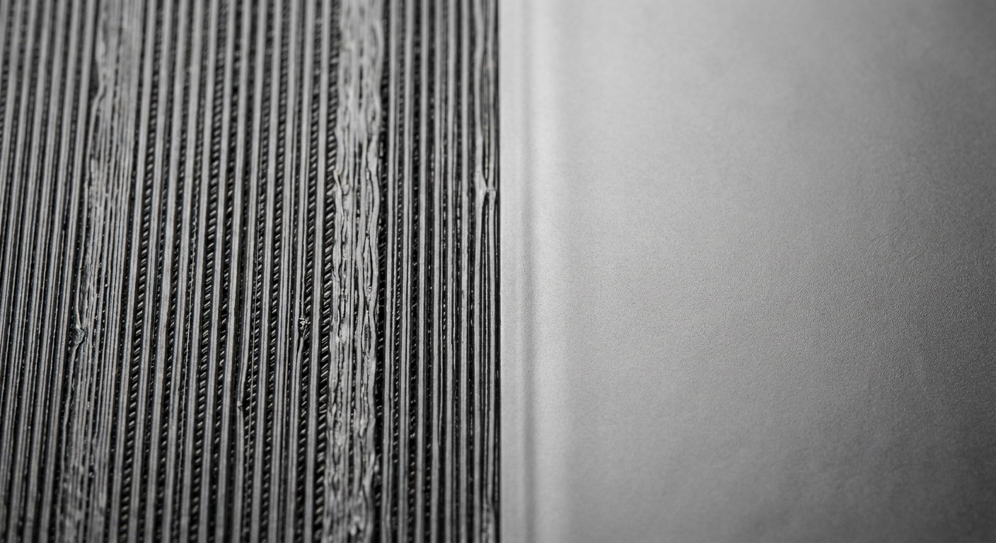
In FDM (Fused Deposition Modeling) 3D printing, achieving a flat, smooth, and refined top surface has historically been a challenge. Standard top layers leave behind parallel extrusion lines, tiny peak-and-valley ridges, and subtle micro-gaps where toolpaths turn.
Ironing in 3D printing is a post-processing slicing feature designed specifically to eliminate these surface artifacts during the printing process itself.
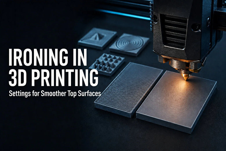
When enabling a slicer ironing top surface pass in tools like OrcaSlicer, PrusaSlicer, or Cura, the print head does not immediately finish the part after extruding the final solid top layer. Instead, the nozzle executes a second, ultra-dense finishing pass directly over the flat top surface. By combining conductive heat from the heated nozzle tip with a tiny trickling stream of molten plastic, ironing smooths out the ridges and fills the microscopic valleys between extrusion paths.
The result is a uniform, satin-to-gloss top finish that can improve both the visual aesthetic and tactile feel of flat 3D printed components.
How Does Ironing Work?
To understand how ironing works, it helps to examine the thermal and mechanical dynamics taking place at the nozzle tip.
Ironing operates on two simultaneous physical mechanisms:
- Thermal Smoothing (Conduction): As the brass or hardened nozzle glides over the recently printed layer, the heated nozzle tip acts as a hot mechanical trowel. Conductive heat transfer re-softens the high points (ridges) of the underlying plastic lines, flattening them downward.
- Micro-Extrusion (Void Filling): Conductive heat alone is usually insufficient to produce a flat plane because small voids remain between adjacent rounded strands. To solve this, the extruder maintains a very low, controlled flow rate (typically 5% to 15% of normal extrusion). This tiny stream of fresh molten polymer fills the microscopic valleys, sealing the top skin.
According to Prusa's technical documentation on top-layer ironing, this secondary pass takes place at the exact same layer height as the final top infill, ensuring no additional Z-height is added to the model dimensions.
Ironing vs. Standard Top-Layer Printing
Ironing differs fundamentally from normal printing passes in feed rate, flow volume, and line overlap.
|
Parameter / Feature |
Standard Top-Layer Printing |
Ironing Finishing Pass |
|---|---|---|
|
Extrusion Flow Rate |
95% – 100% (Full volumetric flow) |
5% – 15% (Micro-fractional flow) |
|
Print Head Speed |
50 – 150+ mm/s |
10 – 30 mm/s (Controlled thermal contact) |
|
Line Spacing (Stepover) |
Equal to line width (0.40 – 0.45 mm) |
Ultra-tight spacing (0.08 – 0.15 mm) |
|
Toolpath Direction |
Typically 45° rectilinear / monotonic |
45° cross-hatch or perpendicular pass |
|
Z-Height Movement |
Advances upward by 1 layer height |
Stays at the same Z-height as the top layer |
|
Primary Objective |
Build solid structural shell thickness |
Flatten surface peaks and seal inter-line voids |
When Should You Use Ironing?
Ironing delivers exceptional aesthetic and functional value in specific applications:
- Display Models & Decorative Items: Badges, coasters, keychains, and decorative plaques where the top face is the primary visual focal point.
- Enclosure Lids & Mounting Plates: Flat functional parts that mate against other smooth surfaces or require a polished appearance.
- Recessed Text & Multi-Color Inlays: Models featuring flat backgrounds surrounding debossed text or dual-extrusion graphic elements.
- Post-Processing Prep: Parts intended for painting or vinyl application, where a smooth substrate minimizes sanding time.
When Should You Avoid Ironing?
While ironing can create smooth top surfaces, applying it indiscriminately can lead to wasted time or ruined prints. Avoid ironing under the following conditions:
- Sloped or Curved Surfaces: Ironing relies on flat, horizontal planar contact. On sloped roofs or organic dome geometry, the nozzle cannot maintain flat contact, resulting in severe stair-step dragging and material burning.
- Tall, Flexible, or Narrow Structures: Because the nozzle exerts continuous lateral pressure over the top layer, tall thin towers or slender flexible parts can wobble under the nozzle, leading to layer shifts or detachment.
- Strict Time Budgets: The ultra-tight line spacing required for ironing increases total print duration. On large build plates, ironing a single flat area can add 30 to 90 minutes to the job.
- Internal / Non-Visual Layers: Ironing non-visible internal surfaces or hidden mating faces consumes time and nozzle wear for zero practical gain.
Suitable vs. Unsuitable Model Geometries
|
Suitable Geometries (Ideal for Ironing) |
Unsuitable Geometries (Avoid Ironing) |
|---|---|
|
Flat horizontal planes (0° slope) |
Curved, spherical, or organic surfaces |
|
Large uniform badges, lids, and coasters |
Stepped inclines or shallow angled roofs |
|
Flat tops with recessed (debossed) text |
Fine raised text or small isolated pins |
|
Mechanical baseplates and mounting faces |
Tall, narrow columns susceptible to flex |
Key Ironing Settings Explained
The values below are starting points rather than universal standards. Ironing results vary with the slicer, nozzle size, filament brand, extrusion calibration, and printer setup. According to Prusa's technical documentation on top-layer ironing, achieving optimal results requires trial-and-error calibration across flow, speed, and line spacing for different materials. Always validate settings with a small test print.
Note that parameter names, default values, and settings paths vary between slicers like OrcaSlicer, PrusaSlicer, and Cura (see OrcaSlicer's official ironing quality documentation for specific OrcaSlicer workflows).
Ironing Flow Rate (%)
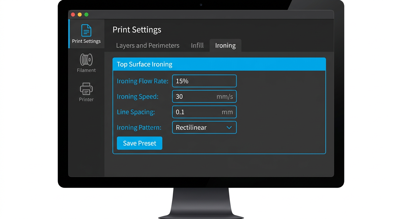
Ironing Flow Rate dictates the volume of filament extruded during the ironing pass, expressed as a percentage of standard layer flow.
- Too Low (<5%): The nozzle does not supply enough plastic to fill the micro-voids between lines. The surface remains rough, showing visible grooves and dull patches.
- Too High (>15%): Excess molten plastic accumulates in front of the nozzle shoulder. This leads to rough plastic ridges, edge overflow, blobbing, and severe nozzle dragging marks.
- Example Starting Point: 10% for PLA, 7% for PETG.
Ironing Speed (mm/s)
Ironing Speed controls how fast the print head traverses the surface during the finishing pass.
- Too Fast (>35 mm/s): The nozzle passes over the plastic too quickly to transfer adequate thermal energy. The plastic fails to soften, leaving uneven textures.
- Too Slow (<10 mm/s): Excessive heat radiates into the underlying top layers, causing localized thermal distortion, heat marks, and filament degradation.
- Example Starting Point: 20 mm/s across most materials.
Ironing Line Spacing (mm)
Ironing Line Spacing (or stepover) defines the distance between adjacent parallel passes during the ironing pattern. As noted in All3DP's breakdown of slicer ironing fundamentals, tighter spacing ensures multiple overlapping thermal smoothing passes.
- Recommended Range: 0.08 mm to 0.15 mm (typically 20% to 30% of your nozzle diameter). A 0.10 mm spacing is a possible starting point for a 0.4 mm nozzle.
Ironing Pattern and Angle
- Pattern: Most modern slicers offer Rectilinear or Zig-Zag patterns. Enabling Monotonic Ironing Order ensures all ironing toolpaths traverse in a single continuous direction, eliminating light reflection bands across the finished part.
- Angle: Many slicers use a 45° ironing angle relative to the underlying top infill lines, although the exact behavior and direction depend on your chosen slicer software.
Ironing Inset (Margin)
Ironing Inset offsets the boundary of the ironing toolpath inward from the outer wall perimeter (typically 0.25 mm to 0.35 mm). This inset prevents the nozzle from pushing molten plastic over the finished outer edge, eliminating small plastic lip bulges along the perimeter.
How to Test Ironing Settings
Because filament brands, nozzle wear, and motion system kinematics vary across individual machines, there are no universal 3D printing ironing settings. A setting that produces a smooth finish on one setup may cause dragging or blobbing on another.
The most efficient approach is to run a controlled, low-material calibration test.
The 15-Minute Calibration Workflow
- Download or Model a Test Tile: Create a simple 30×30×4mm square block in your CAD software or slicer.
- Set Standard Printing Profiles: Slice the test tile with your standard layer height (e.g., 0.2mm), ensuring at least 4 to 5 solid top shell layers so the surface has a firm underlying structure.
- Isolate the Flow Variable: Keep Ironing Speed fixed at 20 mm/s and Ironing Line Spacing fixed at 0.10 mm.
- Print a 4-Tile Array: Duplicate the tile 4 times on your build plate. Set per-object ironing flow rates across the array:
- Tile A: 6% Flow
- Tile B: 9% Flow
- Tile C: 12% Flow
- Tile D: 15% Flow
Inspect Under Directional Light: Examine the finished tiles under a low-angle desk lamp.
- If the tile shows dull patches and visible line gaps, the flow rate is too low.
- If the tile shows rough raised ridges at toolpath turns, the flow rate is too high.
- The winning setting will exhibit a uniform, satin-smooth finish across the entire surface.
Material Guide: Tuning Ironing for PLA, PETG, ABS, and ASA
When comparing ironing PLA vs PETG or high-temperature engineering filaments like ABS and ASA, different polymers exhibit distinct thermal properties, melt viscosities, and surface adhesion characteristics during an ironing pass.
Material-specific values are only example starting points. Adjust them based on the filament manufacturer’s recommendations and your own calibration results.
PLA (PolyLactic Acid)
PLA is the easiest and most forgiving material to iron. It has a sharp glass transition temperature (~60°C) and low melt elasticity, allowing the nozzle to smooth ridges cleanly without pulling or lifting the plastic.
- Ironing Flow: 10% – 12%
- Ironing Speed: 20 – 25 mm/s
- Line Spacing: 0.10 mm
- Cooling Fan: 100% (Full cooling prevents heat buildup in underlying layers)
PETG (Polyethylene Terephthalate Glycol)
PETG is notoriously sticky and prone to accumulating on the nozzle shoulder. If the ironing flow rate is even slightly too high, PETG will stick to the nozzle tip, forming small burnt blobs ("boogers") that drop onto the print surface.
- Ironing Flow: 5% – 8% (Significantly lower than PLA)
- Ironing Speed: 15 – 20 mm/s
- Line Spacing: 0.10 – 0.12 mm
- Key Tweak: Reduce flow rate first if stringing or nozzle accumulation occurs. Ensure your nozzle tip is clean before starting.
ABS and ASA
ABS and ASA may produce good results when the profile is properly tuned due to their high glass transition temperature (~105°C) and structural stability. However, because ironing adds prolonged thermal energy to the top layer, poor ambient temperature control can cause localized warping or surface smearing.
- Ironing Flow: 8% – 10%
- Ironing Speed: 20 – 25 mm/s
- Line Spacing: 0.10 – 0.15 mm
- Key Tweak: Print within an enclosed build chamber with low cooling fan speed (10–20%) to maintain uniform thermal equilibrium across the top skin.
Summary Matrix: Baseline Settings by Material
|
Material |
Ironing Flow Rate (Example Range) |
Ironing Speed (Example Range) |
Line Spacing (Example Range) |
Fan Cooling |
Primary Tuning Objective |
|---|---|---|---|---|---|
|
PLA |
10% – 12% |
20 – 25 mm/s |
0.10 mm |
100% |
Maximize surface smoothness |
|
PETG |
5% – 8% |
15 – 20 mm/s |
0.10 – 0.12 mm |
30% – 50% |
Prevent nozzle stickiness & blobbing |
|
ABS |
8% – 10% |
20 – 25 mm/s |
0.10 – 0.15 mm |
0% – 20% (Enclosed) |
Maintain heat balance & prevent warp |
|
ASA |
8% – 10% |
20 – 25 mm/s |
0.10 – 0.15 mm |
10% – 20% (Enclosed) |
Ensure smooth UV-resistant top face |
Common Ironing Problems and Fixes
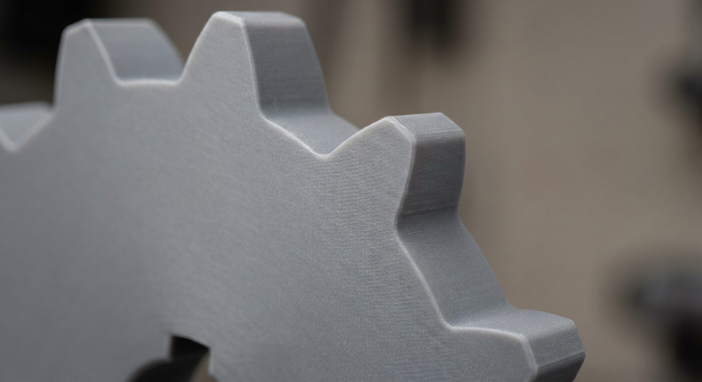
When ironing results fall short of expectations, specific surface artifacts provide clear clues about which parameter needs adjustment.
Diagnostic & Troubleshooting Matrix
|
Observed Defect |
Primary Physical Cause |
Secondary Factor |
Recommended Slicer Adjustment |
Recommended Hardware / Process Action |
|---|---|---|---|---|
|
Rough, Scratchy Lines Remaining |
Insufficient material to fill inter-line voids |
Line spacing too wide |
Increase Ironing Flow by 2–3%; decrease Line Spacing to 0.08mm |
Verify extrusion multiplier and nozzle diameter calibration |
|
Blobs & Raised Plastic Ridges |
Excess molten material pushed ahead of nozzle |
Flow rate set too high |
Decrease Ironing Flow by 3–5%; increase Ironing Inset |
Clean nozzle tip; remove accumulated burnt filament residue |
|
Edge Overflow / Lip Bulge |
Plastic squeezed outward past perimeter walls |
Inset margin too small |
Increase Ironing Inset to 0.30–0.35mm |
Verify outer wall flow rate and pressure advance calibration |
|
Surface Smearing & Discoloration |
Overheating of underlying top skin |
Nozzle dwelling too long in one spot |
Increase Ironing Speed by 5 mm/s; lower printing temp by 5°C |
Ensure cooling fan is operational during top layer passes |
|
Nozzle Dragging / Surface Gouging |
Under-supported top layer or over-extrusion |
Inadequate solid top layers below ironing pass |
Increase Top Solid Layers to 5+; reduce flow rate slightly |
Perform bed leveling calibration and verify Z-offset accuracy |
When dialing in these parameters, using well-maintained open-source hardware and properly calibrated slicer profiles helps maintain consistent extrusion dynamics throughout long calibration runs.
FAQ (Frequently Asked Questions)
Does ironing clog 3D printer nozzles?
Ironing can contribute to heat creep or nozzle buildup on some printers, especially when large areas are ironed at very low flow and slow speed. If you notice under-extrusion during or after ironing, stop the print and check the nozzle and hotend. Always maintain a small positive extrusion flow (typically at least 5%) to keep filament moving through the melt zone.
Does ironing increase print time significantly?
Yes. Because ironing uses an extremely fine line spacing (e.g., 0.10 mm vs standard 0.42 mm line width), the print head must execute roughly 4 times as many passes over the top surface at lower speed. To minimize time impact, many users select Topmost Surface Only in their slicer settings rather than ironing all internal flat surfaces.
Can you iron top surfaces when using a 0.6mm or 0.8mm nozzle?
Yes, but line spacing and flow rate must be scaled accordingly. For a 0.6mm nozzle, set ironing line spacing to roughly 0.15 mm to 0.18 mm. Keep in mind that larger nozzle tips have a wider flat shoulder, which can transfer more heat; you may need to increase ironing speed slightly to prevent surface smearing.
Should I enable ironing for all top surfaces or topmost surface only?
For most exterior-only finishing, start with Topmost Surface Only. Ironing lower internal flat surfaces (like interior floor steps that will be covered by infill or upper structures) usually adds unnecessary print time and thermal stress without offering visual benefits. However, if internal flat steps serve as visible mating faces or functional floors, enabling ironing for all top surfaces can be beneficial.
Final Takeaway
Ironing is one of the most effective slicer tools for elevating FDM 3D prints from raw prototype quality to refined, professional products. By leveraging the hot nozzle tip as a smoothing surface and delivering micro-amounts of filament into top-layer voids, you can achieve remarkably flat, smooth top faces.
Remember that ironing is fundamentally an empirical process. Rather than searching for a universal setting, print a 15-minute calibration tile array whenever you switch filament types or brands. Dialing in your Ironing Flow Rate, Ironing Speed, and Line Spacing on small test parts ensures consistently smooth results on your final, high-value models.