




Designing mechanisms that come off the build plate fully assembled and ready to move is one of the most rewarding capabilities of desktop FDM printing. Print-in-place mechanisms eliminate manual post-assembly, reduce fastener hardware costs, and allow complex captive geometries that would otherwise be impossible to construct from separate pieces.
However, moving from a static CAD model to a functional moving assembly often leads to fused hinges, broken internal pins, or slop in joint movement. Achieving smooth mechanical action requires a clear understanding of FDM extrusion dynamics, slicer compensation, and parametric clearance rules.
This guide details how print-in-place 3D printing works, how to structure mechanical CAD geometry, how to choose baseline clearances, and how to troubleshoot common print-in-place failures.
What Print-in-Place 3D Printing Is and How It Works
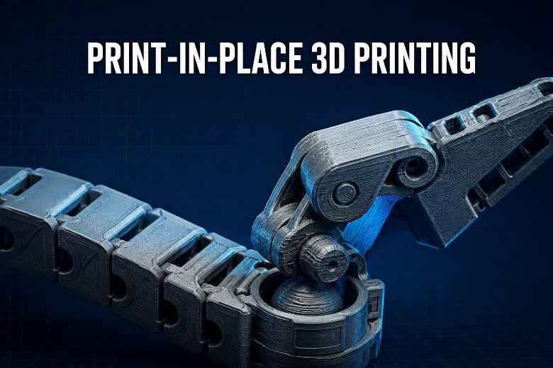
Print-in-place mechanisms are pre-assembled models printed in a single print job. Instead of printing individual links or hinge leaves and joining them with metal pins or screws, the printer constructs both the housing and the internal moving components simultaneously.
The mechanics rely on controlled air gaps—known as clearances or offsets—between adjacent features. During slicing, the slicer generates separate toolpaths for mating parts so that their extruded plastic perimeters do not touch or weld together.
When the nozzle deposits molten filament across a clearance gap, two physical forces determine whether the joint remains free or fuses solid:
- Heat, Ooze, and Overlapping Extrusion: Molten thermoplastic placed too close to an adjacent wall can radiate heat and adhere to neighboring surfaces before solidifying, especially if oozing occurs.
- Extrusion Die Swell and Over-Extrusion: As thermoplastic leaves the nozzle, it expands slightly. If the extrusion width exceeds the CAD air gap, adjacent perimeters overlap and weld together.
To succeed with FDM print-in-place design, the CAD air gap must remain wider than the printer's combined dimensional error, die swell, and first-layer squish.
Types of Moving Parts Suitable for Print-in-Place Designs

Not every mechanical joint translates well to print-in-place fabrication. Geometries must be self-supporting or rely on manageable bridging distances without internal support structures. Three mechanism types are particularly well-suited for FDM print-in-place production:
1. Vertical Pin-and-Socket Hinges
Oriented vertically along the Z-axis, these hinges feature a central cylindrical pin surrounded by an outer sleeve. Because the circular cross-section is sliced in the horizontal X/Y plane, printer motion accuracy is high, and no horizontal bridging is required across the moving gap.
2. Horizontal Teardrop Hinges
When a hinge axis must lie parallel to the print bed (in the X/Y plane), standard circular pins create unsupported horizontal arches that sag into the internal clearance space. Replacing circular holes with a 45° teardrop profile allows the top of the socket to bridge cleanly without dropping molten plastic onto the internal pin.
3. Articulated Chain Links and Captive Ball-and-Socket Joints
Articulated models feature interlocking rings or captive ball joints that retain freedom of motion along multiple axes. These joints use chamfered contact surfaces and self-supporting overhang angles (45° or steeper) to prevent internal overhangs from drooping.
How to Design Hinges, Joints, and Articulated Parts

Creating functional 3D printed moving parts requires specific CAD decisions before slicing.
Maintain Self-Supporting Overhang Angles
Keep critical overhangs at approximately 45° or less from the vertical axis, and validate the result with a test print. Steeper angles cause filament tracks to print in thin air, drooping downward into the clearance gap and welding the joint.
Optimize Pin Orientation and Aspect Ratios
Whenever possible, design rotation pins parallel to the Z-axis. Z-axis pins maintain consistent circularity because X/Y stepper motion is continuous and smooth. Small horizontal pins can be more vulnerable to sagging and layer-direction weakness. If possible, orient the pin vertically or increase its diameter after testing the actual load direction.
Enforce Chamfers on Internal Shoulders
Where an internal pin meets its supporting base, apply a 0.5 mm × 45° chamfer rather than a sharp 90° corner or a small fillet. Sharp internal corners concentrate stress and create toolpath deceleration points that cause localized over-extrusion.
Clearance and Spacing Rules for FDM Printing
Understanding print-in-place clearance requires distinguishing between radial clearance (the offset per side) and total diametral gap (the total difference in diameter between a hole and a pin).
Important: Clearance values are baseline starting points, not universal constants. Optimal clearance varies based on nozzle condition, filament flow rate, layer height, and machine frame rigidity. Always test and calibrate your specific setup.
Recommended Baseline Clearances
These values are starting points for a calibrated 0.4 mm nozzle and 0.2 mm layer height. Actual results vary by printer, material, and slicer profile.
|
Fit Intended |
PLA Clearance (Per Side) |
PETG Clearance (Per Side) |
Total Gap (2 × Per-Side Clearance) |
|---|---|---|---|
|
Tight / Firm Motion |
0.15 mm – 0.20 mm |
0.20 mm – 0.25 mm |
0.30 mm – 0.50 mm |
|
Standard Smooth Rotation |
0.20 mm – 0.30 mm |
0.25 mm – 0.35 mm |
0.40 mm – 0.70 mm |
|
Loose / Free-Swinging |
0.30 mm – 0.40 mm |
0.35 mm – 0.45 mm |
0.60 mm – 0.90 mm |
When designing print-in-place hinges in PLA using a standard 0.4 mm nozzle and 0.2 mm layer height, a radial clearance of 0.25 mm per side (0.50 mm total diametral gap) can be used as a reasonable starting point for testing break-free motion and joint play.
For PETG, increase the radial clearance by 0.05 mm to 0.10 mm per side. PETG exhibits higher surface tackiness and thermal expansion, making tight clearance gaps more susceptible to micro-welding during printing.
How to Account for Elephant's Foot and First-Layer Inaccuracies
Elephant's foot is a common cause of failed print-in-place assemblies. To ensure the first layer adheres firmly to the print bed, slicers push the nozzle slightly closer to the plate or increase first-layer extrusion width. This extra material squishes outward horizontally, bridging internal clearance gaps at the base of the model and fusing moving components at floor level.
   Normal Upper Layers:               Elephant's Foot First Layer:
   | Socket |   | Pin |               | Socket |===| Pin |  <-- Fused at bed!
   |  0.25  |   |     |               |  0.25  |===|     |  <-- Excess squish
Preventing First-Layer Fusion
- CAD Bottom Chamfers: Apply a 0.5 mm to 1.0 mm × 45° chamfer to the bottom edges of both the pin and the surrounding socket. This creates a physical relief zone that absorbs first-layer squish without reducing internal clearance.
- Slicer Compensation: Use the slicer's Elephant Foot Compensation (or XY First Layer Compensation) setting and start with a small value, such as 0.1 mm to 0.2 mm, then adjust it based on the first-layer result. Note that input direction and parameter names may vary by slicer.
- Avoid Rafts or Heavy Brim Contact: Never allow a brim to touch internal moving clearances. If a brim is necessary for bed stability, set a Brim-to-Object Gap of 0.20 mm to 0.25 mm so the brim remains outside moving boundaries.
The Importance of Print Orientation, Bridging, Cooling, and Support Settings
Slicer execution dictates whether well-designed CAD geometry succeeds on the print bed.
Print Orientation
Print the assembly so that moving axes align vertically (along the Z-axis) whenever possible. This places the clearance gaps in the horizontal X/Y plane, where perimeter paths remain distinct and continuous.
Bridging and Cooling Parameters
When a joint geometry requires bridging over an internal gap, the top layer of the void must solidify effectively.
- Start with strong cooling for PLA bridges and run a small bridge test.
- A bridge flow ratio around 0.90 to 0.95 may help reduce sagging on external bridges, but the optimal value depends on the specific material and printer.
Support Structure Boundary Rules
Avoid generating support structures inside print-in-place clearance gaps whenever possible. Support interfaces leave rough surface scars that can lock joints permanently.
- Use Support Blockers in your slicer over all moving joint voids.
- Ensure the CAD design remains strictly self-supporting so automatic support generation is unnecessary.
How Material Choice Affects Moving Parts: PLA vs. PETG
Material properties dictate clearance tolerance selection, bridging cleanliness, and wear resistance in articulated 3D prints.
|
Material Modulus & Stringing Behavior |
Detail |
|---|---|
|
PLA |
High Stiffness - → Crisp Bridging - → Standard Clearance (0.25mm) |
|
PETG |
High Toughness - → Prone to Stringing -> Larger Clearance (0.35mm) |
Polylactic Acid (PLA)
PLA is the most forgiving thermoplastic for print-in-place mechanisms. Its high flexural modulus and sharp thermal transition allow clean bridging across internal gaps with minimal stringing.
- Advantages: Excellent dimensional stability, minimal shrinkage, crisp edge definition.
- Drawbacks: Brittle under sudden impact; lower fatigue resistance for flexural living hinges.
Polyethylene Terephthalate Glycol (PETG)
PETG provides superior impact resistance and thermal durability, making it ideal for functional tools and outdoor hinges. However, PETG is prone to stringing and oozing. Fine strings left inside a 0.20 mm gap can act as reinforcement fibers that weld moving parts together.
- Advantages: High toughness, good chemical resistance, higher temperature tolerance.
- Drawbacks: Requires wider clearances (+0.05–0.10 mm per side) and strict moisture management.
Filament Preparation Tip: Moisture can contribute to PETG stringing and may make small clearances harder to keep clean. Follow the filament manufacturer’s drying recommendations. A filament dryer such as the Sovol SH02 filament dryer box can be used as part of the filament-preparation workflow.
Recommended Slicer Settings for a Reasonable Starting Point
Use these baseline slicer settings when preparing how to design print-in-place parts for first-article testing:
-
Layer Height:
0.16 mmto0.20 mm(finer layers produce cleaner Z-axis rounded surfaces). -
Wall Generator:
Arachne(dynamically adjusts extrusion width in tight spaces to prevent internal over-filling). -
Perimeter Wall Order:
Inside-to-Outside/Inner/Outer(ensures outer perimeter dimensions are placed accurately without being pushed outward by infill). -
Elephant Foot Compensation:
0.1 mmto0.2 mm(adjust based on test print results). -
Bridge Flow Ratio:
0.90to0.95for external bridges (test and adjust for internal bridges). -
Print Speed:
40 mm/sto60 mm/sfor outer perimeters (reducing speed improves dimensional accuracy around small pins). - Cooling Fan: Start with high cooling for PLA bridges, then tune the fan speed based on a small bridge test. PETG may require a different cooling profile.
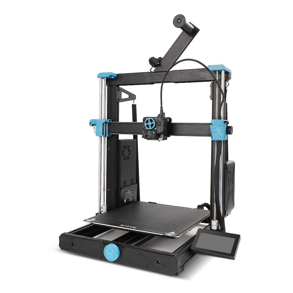
With its 500 × 500 × 500 mm³ build volume and full linear rails, the Sovol SV08 Max CoreXY printer can be considered for large print-in-place assemblies. However, final fit still depends on bed condition, slicer settings, material behavior, and calibration.
Common Problems and Solutions
When troubleshooting 3D printed moving parts, systematic adjustments produce faster results than guessing. Use this diagnostic table to isolate root causes:
|
Observable Problem |
Primary Root Cause |
Recommended Fix |
|---|---|---|
|
Joint fused at first layer |
Elephant's foot / first-layer squish |
Add 0.5 mm bottom chamfer in CAD; set Elephant Foot Comp to 0.1–0.2 mm. |
|
Joint fused throughout model |
Insufficient clearance or over-extrusion |
Increase clearance by +0.05 mm per side; calibrate extruder flow rate. |
|
Moving part is too loose / wobbly |
Excessive clearance offset |
Reduce radial clearance in CAD by 0.05 mm steps. |
|
Pin breaks when breaking free |
Weak Z-axis layer adhesion or sharp corner |
Increase wall count to 3-4; add 0.5 mm × 45° chamfers to pin shoulders. |
|
Rough action / grinding motion |
Sagging bridges or PETG stringing |
Reduce bridge flow ratio slightly; dry filament; adjust bridge cooling. |
|
Model corners lifting / warping |
Bed adhesion loss / thermal contraction |
Clean print bed; use brim with 0.20 mm gap away from moving joints. |
1. Hinges or Joints Fused Together
If the joint refuses to budge after cooling, check where the fusion occurred. If the top and middle move but the base is solid, the issue is first-layer squish. Increase Elephant Foot Compensation or add a bottom chamfer. If the joint is welded along its full height, your printer's extrusion multiplier is too high, or the CAD clearance is tighter than your printer's mechanical tolerance.
2. Moving Parts That Are Too Loose
Excessive slop occurs when clearances are too generous. Reduce the CAD radial clearance in 0.05 mm increments. Switching the slicer wall generator from Classic to Arachne can also prevent the slicer from dropping thin wall gaps that artificially loosen fits.
3. Weak or Broken Hinge Arms
Small internal pins printed vertically can shear along layer lines when subjected to initial break-free torque. Increase the number of perimeter walls to 3 or 4 so the pin consists entirely of concentric continuous perimeters rather than sparse infill.
4. Rough Surfaces and Excessive Friction
A gritty or grinding feel inside a joint indicates sagging bridge lines or stringing. Lower your print temperature slightly, increase cooling fan speed, and tune the bridge flow ratio to keep overhead bridge strands flat.
5. Warping or Failed First Layers
Uneven bed heating causes long print-in-place models to warp at the edges, lifting the joint base and altering internal alignment. Ensure the print bed is thoroughly cleaned with isopropyl alcohol, keep ambient drafts away from the printer, and avoid placing brim lines directly across moving clearance lines.
A Simple Testing Workflow Before Printing Large Models
Never commit a multi-hour or multi-hundred-gram print job to an unverified clearance setting. Implement this 3-step testing protocol first:
- Model a Stepped Test Coupon: Create a small test block containing identical hinge pins with varying radial clearances (e.g., 0.15 mm, 0.20 mm, 0.25 mm, and 0.30 mm).
- Print and Evaluate Break-Free Force: Print the test block using your intended material and layer height. Apply gentle, controlled force and stop if the joint does not release easily. Note which pin releases cleanly and rotates smoothly without excessive play.
-
Lock the Calibrated Parameter in CAD: Assign the winning clearance value to a global variable or user parameter in your CAD software (e.g.,
Joint_Clearance = 0.25mm). Every hinge and joint in your main model will automatically inherit this tested value.
Frequently Asked Questions (FAQ)
What is a reasonable starting clearance for a print-in-place hinge?
For a calibrated 0.4 mm nozzle and 0.2 mm layer height, 0.25 mm radial clearance per side (0.50 mm total diametral gap) can be used as a starting point for PLA. For PETG, start around 0.30 mm per side. Always validate the result with a small test coupon.
How do I break free a newly printed print-in-place joint?
Allow the print to cool completely to room temperature before attempting motion. Apply gentle, controlled force by hand or with padded pliers, and stop if the joint does not release.
Should I use supports on print-in-place models?
Avoid generating support structures inside print-in-place clearance gaps whenever possible. Support structures generated inside moving gaps leave rough surface scars that lock joints permanently. Print-in-place models should be designed with self-supporting angles (45° or less from vertical) so internal supports are unnecessary.
Why do my print-in-place hinges fuse only on the bottom layer?
This is caused by elephant's foot (first-layer squish). To fix it, add a 0.5 mm × 45° chamfer to the bottom edge of all mating parts in CAD, and configure Elephant Foot Compensation in your slicer.
Conclusion and Practical Takeaways
Designing reliable print-in-place mechanisms is a systematic engineering process rather than guesswork. By pairing proper parametric geometry with deliberate slicer settings, you can produce clean, functional moving assemblies with more repeatable results.
Key Summary Rules
- Calibrate Before Printing: Always print a small clearance test coupon to verify tolerances for your specific filament spool and machine setup.
- Defeat Elephant's Foot: Use a 0.5 mm bottom chamfer and positive slicer first-layer compensation to protect the base of moving joints.
- Use Self-Supporting Geometry: Design internal overhangs at approximately 45° or less from vertical or use teardrop profiles to eliminate the need for internal supports.
- Tune Slicer Bridging: Tune bridge flow ratios and bridge cooling to keep overhead strands flat and free from joint pins.
- Adjust for PETG: Add 0.05 mm to 0.10 mm extra clearance per side when switching from PLA to PETG, and follow proper filament drying procedures to manage stringing.
With these clearance principles and slicer calibrations established, you can approach your next moving mechanism design with greater confidence.