




Key Takeaways:
- Inspecting the sliced preview before printing helps reveal potential geometry and toolpath problems, reducing wasted filament and some avoidable print failures.
- Vertical layer sliders and horizontal path sliders let you scrub toolpaths to verify bed contact, overhang angles, support gaps, and thin wall integrity.
- Color-coded preview modes (Line Type, Speed, Flow Rate, and Layer Height) reveal hidden physical bottlenecks like hotend volumetric flow limits.
- A quick preview check can help reduce avoidable failures.
Clicking "Slice" and immediately hitting "Print" is a gamble every 3D printing enthusiast eventually loses. You come back hours later to a bird’s nest of spaghetti filament, a knocked-over support tree, or a wall that vanished because it was thinner than your nozzle diameter.
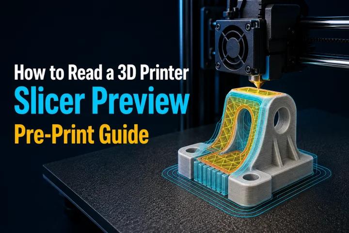
A 3D printer slicer preview visualizes the G-code commands your printer will execute. Learning how to read a 3D printer slicer preview lets you catch mechanical errors, geometry dropouts, and structural flaws in software before consuming a single gram of filament.
Whether you use OrcaSlicer, PrusaSlicer, or Ultimaker Cura, the basic toolpath principles are similar across most FDM slicers. While user interfaces vary across software, these diagnostic principles are broadly applicable.
Why You Should Always Check the Slicer Preview
When you import an STL or 3MF file, the CAD model looks solid and complete. However, FDM 3D printers do not print 3D CAD geometry; they extrude continuous lines of molten thermoplastic along calculated 2D toolpaths stacked along the Z-axis.
The slicing engine translates CAD features into physical line widths based on nozzle size, extrusion multipliers, and layer height. Critical details often get lost during this conversion:
- Thin walls under nozzle width might be skipped entirely by the toolpath engine.
- Overhangs beyond sustainable angles can end up extruding plastic into thin air.
- Z-seams can align across a smooth face, creating a prominent vertical scar.
- Travel moves across open gaps can drag stringy filament across visible outer surfaces.
Inspecting your slicer preview gives you an X-ray view of the print, bridging the gap between digital CAD design and physical extrusion dynamics.
Understanding the Layer Slider and Toolpath Navigation
Every modern slicer preview screen features two primary navigation controls: a vertical layer slider along the right side and a horizontal path slider along the bottom.
The Vertical Layer Slider (Z-Axis Scrubbing)
The vertical slider lets you navigate up and down through the model's Z-height, layer by layer. Dragging the handle reveals how internal geometry, infill patterns, and support towers evolve from the build plate to the top surface. Keyboard shortcuts (such as Up/Down arrow keys) allow precise step-through of individual layers. Pay attention to the Layer Number and Z-Height (mm) readout to identify exact heights where features change or supports terminate.
The Horizontal Path Slider (Toolpath Execution)
While the vertical slider selects a single layer, the horizontal slider at the bottom scrubs through the nozzle execution sequence within that layer. Dragging this slider simulates the exact path the printhead takes, from initial retraction points to inner walls, outer perimeters, infill, and travel moves. Observing the sequence verifies whether your printer executes inner walls before outer walls (improving overhang stability) or outer walls first (optimizing dimensional accuracy).
How to Inspect First and Last Layers

The first layer establishes bed adhesion, while the last layer determines top-surface aesthetic quality. Both require dedicated inspection before starting long prints.
Checking the First Layer (Layer 1)
Switch your vertical slider to Layer 1 and rotate the camera to view the model directly from underneath. Verify that all intended base features make solid contact with the build plate. Look for hollow pockets or isolated islands that lack sufficient surface area. For models prone to warping, verify that your brim lines attach directly to the outer perimeter without an unwanted air gap. Ensure first-layer toolpath lines run edge-to-edge without unexplained gaps. If you struggle with bed contact, review our practical guide on fixing first layer adhesion issues.
Inspecting Top Surfaces (Final Layers)
Drag the layer slider to the top of your model to examine the solid top shell. Use enough top thickness for the model and material. The required layer count depends on layer height, infill pattern, and model geometry. If the preview shows sparse infill peeking through, increase your top solid layer count. If top-surface ironing is enabled, the preview will display ultra-dense, ultra-thin travel lines across the top layer. Verify ironing is applied strictly to "Topmost Surfaces Only" rather than every internal step.
How to Inspect Walls, Gaps, and Perimeters
Walls (perimeters or shells) form the structural boundary of your 3D print
Outer vs. Inner Perimeter BoundariesAlways verify that your shell count matches functional requirements:
- Decorative prints can use 2 to 3 perimeters as a starting baseline.
- Load-bearing functional parts generally benefit from 4 or more perimeters to resist mechanical bending and fastener compression.
- Check that inner perimeters form continuous loops behind the outer perimeter. Fragmented dots indicate fluctuating CAD wall thickness.
Spotting Missing Walls and Thin Wall Gaps
A common slicing error occurs when a CAD feature is narrower than your nozzle's extrusion width (e.g., a 0.3mm wall sliced with a 0.4mm nozzle setting).
- Classic Wall Generators: Fixed-width algorithms may ignore walls thinner than default line width, leaving empty gaps in your preview.
- Arachne Wall Engine: Modern slicing engines incorporate variable line-width algorithms (such as Arachne) to improve thin wall rendering, text clarity, and small logo details. Note that exact implementation details vary across software programs (see PrusaSlicer Arachne Perimeter Generator Documentation). In preview, check whether Arachne generates a continuous thin extrusion or unexpected micro-moves.
Checking Infill and Internal Structures

Infill provides internal rigidity and supports top solid layers. Inspecting infill in preview ensures your part balances structural strength with material efficiency.
Infill Pattern and Anchoring
Scrub through mid-height layers to check how infill interacts with internal perimeters. Verify that infill lines overlap or anchor securely into the inner perimeter wall. Unanchored lines that stop short of walls provide zero structural reinforcement. Patterns like Grid or Triangles extrude crossing lines on the same layer, which may increase the risk of nozzle dragging during high-speed printing. Non-crossing 3D patterns like Gyroid or Cubic appear as fluid curves in preview and can help reduce nozzle scraping.
Top Layer Support over Sparse Infill
If infill density is set too low, inspect the first solid top layer directly above the infill. Look for long, unsupported line spans bridging across wide infill cells. If span gaps become excessive, plastic will sag between infill walls (pillowing). To fix this, increase infill density or select an appropriate pattern provided by your slicing software. For a deeper breakdown of structural tuning, check our reference on optimizing infill density and shell strength.
Reviewing Supports and Overhangs
Unprinted overhangs and ungrounded support structures are common causes of failed print starts.
Identifying Steep Overhangs and Floating Islands
Rotate your camera underneath the sliced model and check for overhang highlighting. Overhang performance depends on material properties, cooling airflow, layer height, printing speed, and model geometry. Note that slicing programs define overhang angles differently; for instance, PrusaSlicer measures support angles relative to the horizontal plane (see PrusaSlicer Support Material Guide). Look for floating islands—toolpath lines that start in mid-air with no underlying plastic or support underneath. Floating islands are likely to print poorly without support beneath them.
Evaluating Tree vs. Normal Supports
Review support structures in your preview interface:
- Normal (Grid) Supports: Form rigid vertical walls directly underneath overhangs. Confirm they do not fuse into detailed surface features.
- Tree (Organic) Supports: Form tapered trunks that branch around the model to support overhangs from the build plate. Inspect the preview to ensure tree branches do not pass dangerously close to outer walls.
- Support Interface Gap: Zoom in on the boundary where support meets the model. Verify that an adequate vertical air gap (support Z-distance) exists based on your layer height, material choice, and slicer preset. Without an appropriate gap, supports can weld permanently to your part. For detailed interface configuration, refer to our step-by-step tutorial on customizing 3D printing supports.
Understanding Travel Moves and Seam Placement
Extrusion lines show where plastic is deposited; non-extrusion lines show where the toolhead travels between extrusions.
Inspecting Non-Extrusion Travel Paths
In OrcaSlicer, PrusaSlicer, and Cura, travel moves appear as vectors connecting extrusion endpoints. Enable the Travel checkbox in your preview legend to make these paths visible. Look for long travel paths that cross open air gaps or pass over finished top surfaces, which lead to stringing and oozing. Enable options like "Avoid Crossing Perimeters" or "Combing" to reduce travel paths across outer walls (see PrusaSlicer Layers and Perimeters Guide). Note that these functions focus on reducing outer wall crossings rather than keeping every single travel move inside internal infill boundaries.
Reviewing Z-Seam Alignment
Every closed perimeter loop must start and end at a specific point on the model, creating a subtle vertical seam marked by dots in previews. Confirm seam points hide neatly inside sharp concave or convex corners. Avoid random seam placement on smooth models, as it scatters unsightly zits across the outer surface. Some slicers also offer scarf seams as an optional feature to gradually taper extrusion flow at perimeter joints. Learn more in our guide on adjusting Z-seam placement settings.
Using Color-Coded Preview Modes
Slicers provide a drop-down selector in the preview window to switch between different visualization color maps. Always refer to your specific software's legend menu to verify line types and parameter color codes:
1. Speed Preview Mode (mm/s)
Displays a color spectrum representing speed variations. Verify that outer perimeters print at a consistent, moderate speed for smooth surface quality, and check that small features and sharp corners automatically slow down.
2. Flow Rate / Volumetric Speed Mode (mm³/s)
Measures the volume of plastic extruded per second (Line Width × Layer Height × Speed). High-contrast bands on wide infill moves signal that requested speed may approach or exceed hotend melting capacity, risking extruder skipping and under-extrusion.
3. Layer Height Mode (Adaptive Layering)
Highlights smooth gradients showing where layer heights thin down (for fine curves) or thicken up (for fast vertical walls).
Checking Print Time and Filament Usage
Before exporting your G-code file, inspect the summary panel displayed in the preview window.
Estimated Print Time Breakdown
Expand the feature-by-feature time breakdown next to the estimated print time to identify bottlenecks. See what percentage of print time is spent on outer walls, infill, supports, or travel moves. If supports consume 40% of total print time, reorienting the model or switching to Tree supports can dramatically reduce print duration.
Filament Weight, Length, and Cost
The slicer estimates material consumption in grams, meters, and estimated currency cost. Verify that you have enough spool weight remaining before starting a long print.
Spotting Build Area Collisions
If any part of your model, brim, or support extends past the printable bed area, the sliced preview will render in solid grey or display red warning crosshatches. On multi-color prints, ensure the wipe/purge tower does not collide with model boundaries or bed probe clearance margins.
Common Problems Found in Slicer Preview
The following diagnostic table maps visual signs seen in your slicer preview to their underlying causes and corrective actions:
|
Preview Sign |
Likely Cause |
Recommended Action |
|---|---|---|
|
Missing wall loops or empty gaps in thin sections |
Feature thickness is smaller than default nozzle extrusion line width. |
Enable Arachne Wall Generator or adjust line width settings. |
|
Toolpath lines floating in mid-air (no underlying plastic) |
Unsupported overhang angle or ungrounded model geometry. |
Enable Supports, reorient the model on the build plate, or add a manual support enforcer. |
|
Seam dots scattered randomly on smooth outer surfaces |
Z-seam alignment is set to "Random". |
Change Z-seam placement to "Aligned", "Rear", or "Sharpest Corner". |
|
Long travel lines crossing open air gaps |
Retraction/combing disabled, or perimeter avoidance turned off. |
Enable Avoid Crossing Perimeters / Combing, or increase retraction travel threshold. |
|
High-flow color alerts in Volumetric Flow preview mode |
Requested speed exceeds hotend melting capacity. |
Reduce print speed or adjust maximum volumetric speed settings. |
|
Top solid layers show hollow gaps over infill |
Insufficient top solid layer count or infill density set too low. |
Increase top solid layers or increase infill density. |
|
Support structures welded directly to the model body |
Top Support Z-Distance set without sufficient air gap. |
Adjust Support Top Z-Distance according to layer height and preset recommendations. |
|
Model renders in solid grey with no extrusion toolpaths |
Model exceeds physical bed bounds or sits slightly below the build plate. |
Re-center model, scale down slightly, or use the "Place on Face" tool. |
A Pre-Print Slicer Checklist
Follow this concise 10-step checklist before sending any G-code file to your FDM 3D printer:
- Verify Orientation: Confirm the model is positioned as intended and that all required base contacts and supports are present.
- Layer 1 Check: Scrub to Layer 1 from underneath; verify continuous bed contact and brim attachment.
- Shell Count: Confirm perimeter count matches functional requirements for decorative or structural strength.
- Thin Wall Scan: Zoom in on narrow details; confirm Arachne or wall settings haven't dropped thin walls.
- Infill Integrity: Ensure the infill pattern anchors firmly into inner walls and supports top layers cleanly.
- Overhang & Island Check: Scan bottom surfaces for overhang warnings or ungrounded floating lines.
- Support Interface Gap: Confirm a vertical air gap separates support interface tops from the model body.
- Z-Seam Placement: Check seam dots; ensure they align in sharp corners or hidden rear faces.
- Travel Path Scan: Verify travel lines stay managed to minimize outer surface stringing.
- Volumetric Flow & Time Check: Confirm peak volumetric flow stays within your hardware limits and material is available.
Toolpath Diagnostics: Corrected vs. Problematic Slicing
Figure: Catching structural and toolpath errors in preview mode before sending files to your printer ensures clean extrusions and reliable prints.Frequently Asked Questions
Why does my model look solid in 3D view but has missing parts in preview?
This happens when CAD features are thinner than your nozzle's minimum extrusion line width (e.g., a 0.2mm feature sliced with a 0.4mm nozzle). In "Classic" slicing mode, the slicer ignores features it cannot fill. To resolve this, switch your wall generator setting to Arachne or decrease line width settings.
What is the difference between Layer Height and Line Width in preview?
Layer Height (Z-axis) controls the vertical thickness of each stacked slice (e.g., 0.2mm), affecting print speed and vertical curve resolution. Line Width (X/Y plane) controls the horizontal thickness of the extruded plastic bead (e.g., 0.45mm from a 0.4mm nozzle), determining wall strength and horizontal detail resolution.
Why are travel lines showing up across my model in preview?
Travel lines (non-extrusion moves) show the path the printhead takes when moving between print points. If travel lines cross open space, your printer may drag thin strings of plastic across the print. Enable settings like "Avoid Crossing Perimeters" or "Combing" to reduce travel moves crossing outer walls.
Can I trust the estimated print time in the slicer preview?
Modern slicer time estimates are close approximations because they calculate motion controller acceleration, jerk, and speed limits based on configured firmware settings. If actual print time differs, verify that your slicer's machine limits match your printer's firmware configuration.
Final Takeaway
Mastering how to read a 3D printer slicer preview converts 3D printing from a trial-and-error guessing game into a repeatable engineering process. Taking 60 seconds to scrub through your layer slider, inspect first-layer adhesion, check overhang support gaps, and verify volumetric flow rates will save you hours of failed prints and spools of wasted filament.
Before starting your next major project, open your preview tab, run through the 10-step checklist, and catch your print problems in software before they happen on the build plate.