




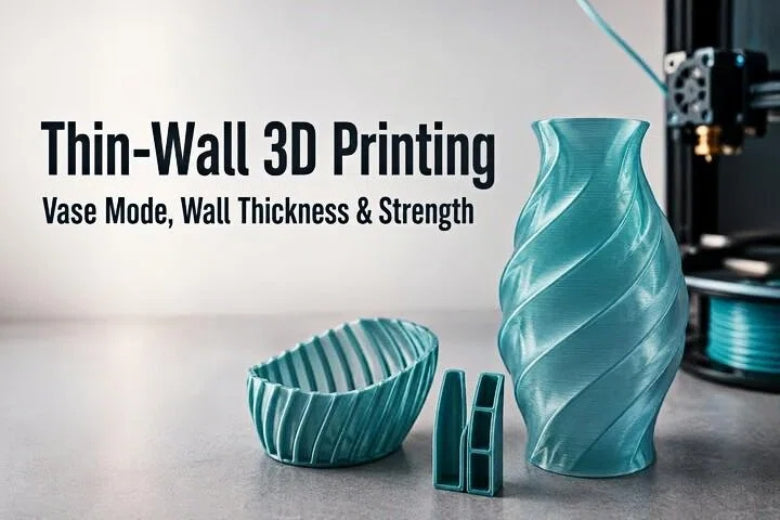
Key Takeaway: Mastering thin-wall 3D printing requires aligning your CAD wall dimensions with your slicer's extrusion line width. While vase mode produces rapid, seam-free single-wall prints, functional components rely on multi-wall perimeters, strategic geometric ribs, and balanced cooling to achieve structural strength without adding unnecessary mass.
Designing lightweight, high-precision parts is one of the most rewarding capabilities of fused deposition modeling (FDM). Whether crafting semi-translucent lampshades, aerodynamic covers, or custom enclosures, thin-wall 3D printing saves material, cuts print times, and reduces weight.
However, printing thin walls presents distinct engineering challenges. If a feature is designed slightly too thin, your slicer might drop it entirely. If printed with improper parameters, the model can buckle, warp, or split along layer lines under light pressure. To consistently produce rigid, high-quality parts, you must understand how CAD design rules, slicer settings, and mechanical forces interact.
This guide details everything you need to know about designing and printing 3D printed thin walls, comparing single-wall approaches like vase mode against multi-wall strategies, and tuning your settings for maximum strength.
What Is Thin-Wall 3D Printing?
In FDM additive manufacturing, thin-wall 3D printing refers to producing vertical or sloped geometry where the shell thickness approaches the physical limits of a single nozzle pass—typically between 0.4 mm and 1.6 mm. Unlike standard solid or infill-backed parts, thin-wall structures rely almost entirely on their outer perimeters for shape integrity and mechanical strength.
When printing a standard functional component, your slicer fills the interior space between outer walls with an infill lattice like gyroid or grid. In thin-wall designs, there is often no space for infill. The entire structure consists of one, two, or three continuous extrusions placed side by side.
Because there is no internal lattice to absorb impact, every layer line in a thin wall must bond cleanly to adjacent extrusions. Achieving a successful result requires balancing thermal management, material flow, and geometry.
Thin Walls vs. Vase Mode
When working with slender geometries, desktop FDM printing offers two primary approaches: standard single-wall or multi-wall printing, and dedicated vase mode 3D printing (often called spiralize outer contour in slicers). Understanding the mechanical and practical differences between these two modes is essential before starting a print job.
How Single-Wall 3D Printing Works
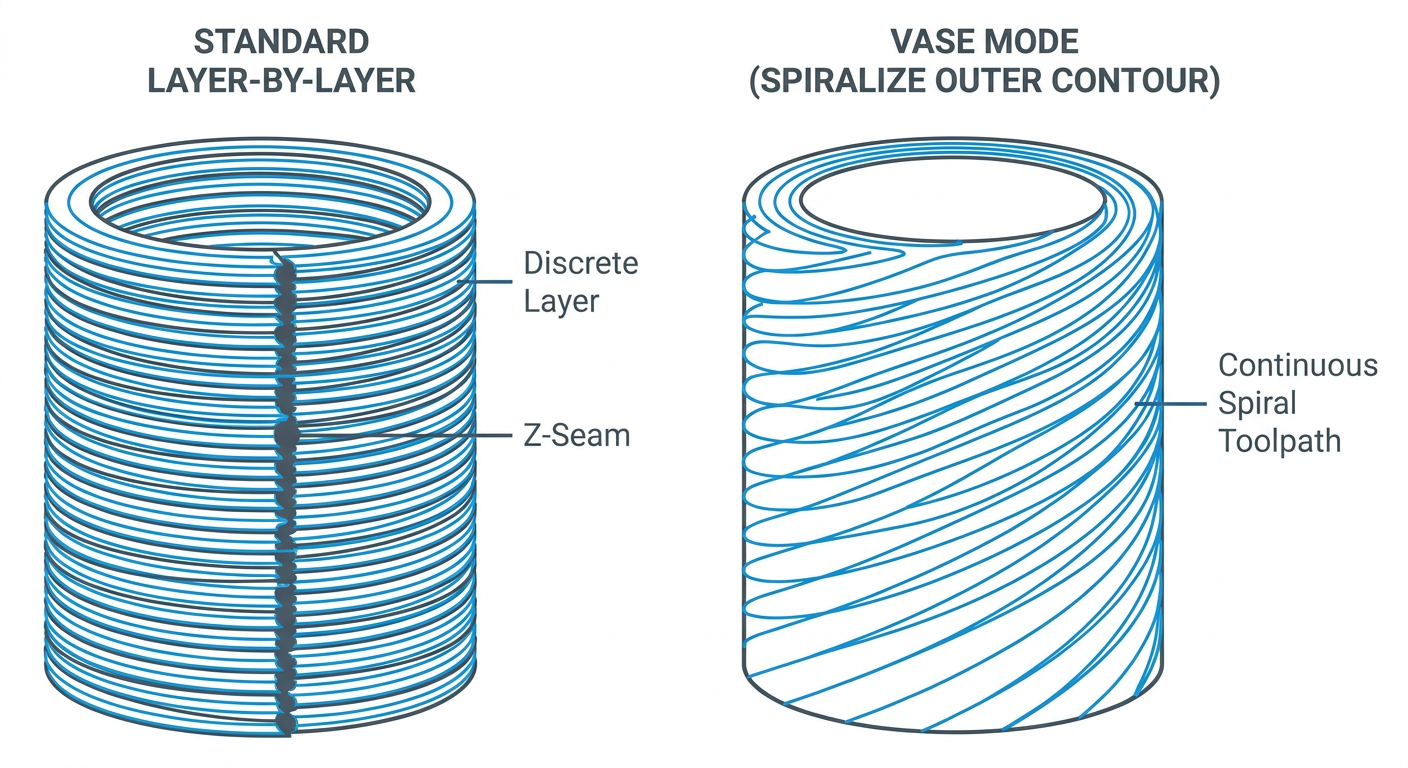
Standard single-wall 3D printing forces the slicer to lay down exactly one perimeter loop per layer. The toolhead follows a traditional toolpath: it moves to a start point, extrudes a complete outer boundary, performs a retraction, steps up along the Z-axis, and starts the next layer.
Because standard single-wall prints utilize discrete layer moves, they produce a visible vertical z-seam where each layer starts and ends. Standard single-wall setups support flat bottoms, internal features, and complex geometries, but retractions can introduce tiny micro-gaps along the seam.
When to Use Vase Mode
Vase mode changes how your printer moves along the Z-axis. Instead of printing discrete horizontal slices, vase mode moves the toolhead in a smooth, continuous spiral upward, continuously raising the Z-axis while extruding filament along the XY path.
This continuous spiral movement offers three major benefits:
- Zero Z-Seams: Because the nozzle never stops extruding or jumping layers, the outer surface is completely smooth.
- Fast Print Speeds: Without retractions or layer transition pauses, print times drop significantly.
- Reduced Seam Leak Paths: Vase mode can reduce seam-related leak paths, but it is not automatically watertight. Any part intended to hold liquid should be tested before use, and direct use for pressure, food contact, or medical applications should be avoided.
However, vase mode imposes strict geometric limits. It requires a model with a single, continuous outer contour and an open top. It cannot slice objects with internal dividers, overhangs that exceed the slicer’s configured overhang limit, or multiple separate spires.
Strength and Flexibility Limitations
While vase mode creates visual appeal, it is important not to assume vase mode is suitable for every model. A single extruded line of filament remains inherently flexible and susceptible to cracking along layer lines when twisted or squeezed.
Because vase mode relies on a single continuous perimeter, forces applied perpendicular to layer lines create high tensile stress across a tiny contact area. If your application demands impact resistance or load-bearing capability, a standard multi-wall perimeter setup is vastly superior.
|
Feature / Metric |
Standard Multi-Wall Printing |
Vase Mode (Spiralize Contour) |
|---|---|---|
|
Wall Construction |
2 or more parallel perimeter lines |
1 continuous helical perimeter line |
|
Z-Seam Appearance |
Visible seam (unless hidden) |
Largely eliminates the vertical Z-seam found in layer-by-layer printing |
|
Mechanical Strength |
Moderate to High |
Low (flexible, prone to splitting) |
|
Print Speed |
Standard |
Often faster for suitable open-top models |
|
Geometry Limits |
Complex shapes, holes, internal ribs |
Continuous open-top single shells only |
|
Watertightness |
Requires tuned overlap & seams |
May reduce seam-related leak paths |
How to Choose the Right Wall Thickness
A common mistake when designing for FDM is picking an arbitrary CAD wall thickness—such as 1.0 mm—without accounting for hardware settings. To achieve clean, gap-free perimeters, your wall thickness should always align with your 3D printer wall thickness variables and line width.
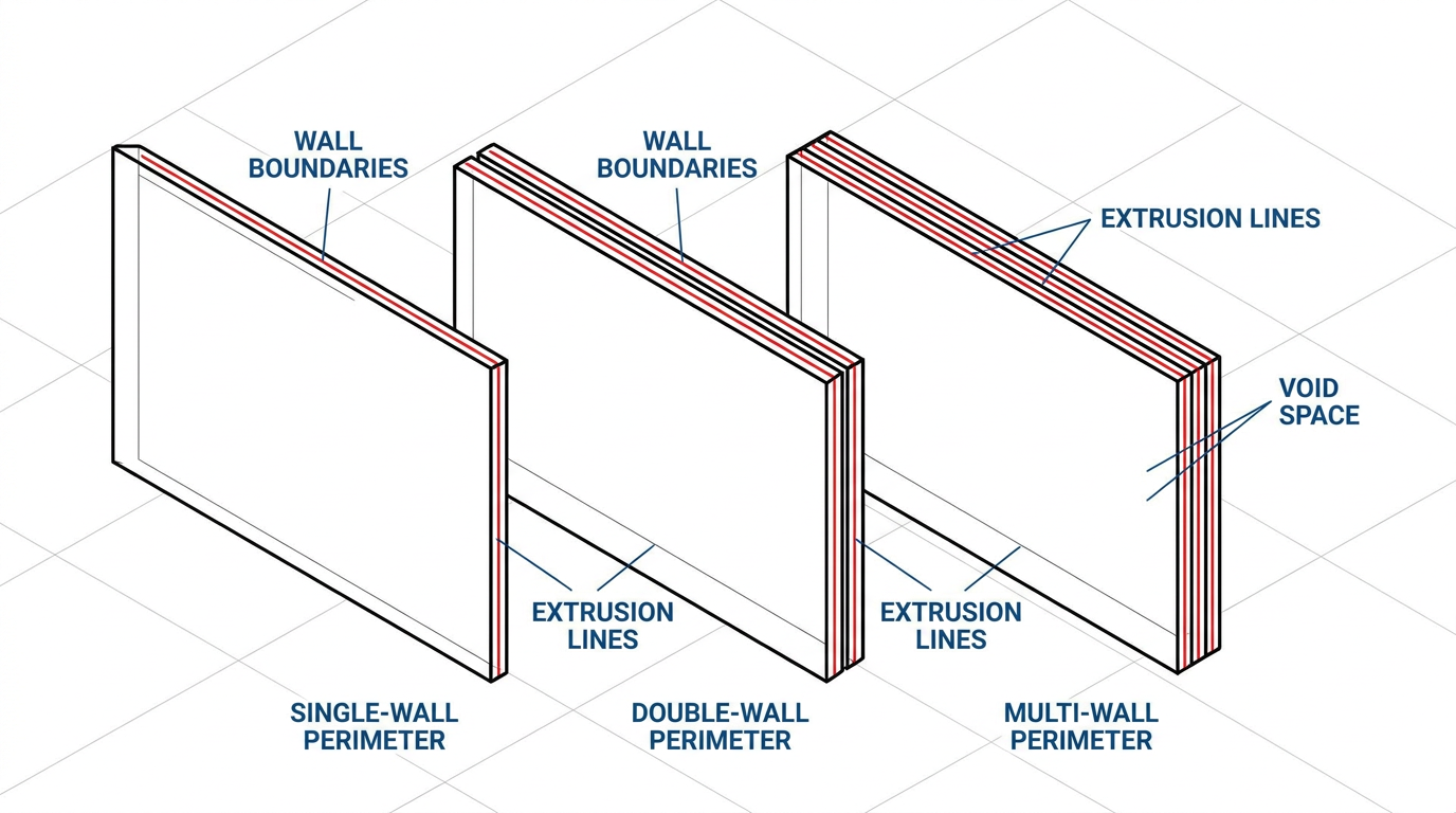
Relationship Between Nozzle Diameter and Line Width
Nozzles flatten extruded plastic against the prior layer, creating an extrusion line width that is typically 10% to 20% wider than the physical nozzle orifice. For example, a standard 0.4 mm nozzle is commonly set in slicers to extrude a line width of 0.45 mm.
If you design a wall in CAD that measures exactly 0.90 mm, your slicer cleanly lays down two equal passes of 0.45 mm with zero wasted motion or hollow gaps:
CAD Wall Target = Number of Perimeters × Extrusion Line Width
If you instead design a wall at 0.70 mm using a 0.45 mm line width setting, the slicer cannot fit two full 0.45 mm passes inside 0.70 mm, leaving potential gaps or uneven toolpaths.
Why There Is No Universal Minimum Wall Thickness
There is no single universal minimum wall thickness that applies across all printers and projects. The minimum printable wall depends on several dynamic factors:
- Nozzle Diameter & Line Width: Smaller nozzles allow finer feature resolution, but minimum printable geometry always depends on physical extrusion width and material flow behavior.
- Slicer Wall Generator: Modern slicers featuring variable line width engines (like Arachne) dynamically adjust line width for non-integer walls. Classic engines rely on exact multiples or thin-wall detection settings.
- Application Demands: Non-load-bearing decorative parts can use thinner single-wall or double-wall shells, whereas functional electronics housings typically require thicker multi-wall perimeters.
The actual minimum wall thickness depends on the nozzle, line width, slicer, material, flow calibration, and model geometry. Always check the sliced preview before printing.
How Material Flow and Calibration Affect the Result
Even with accurate CAD dimensions, improper flow rate (extrusion multiplier) compromises thin walls. Under-extrusion creates microscopic voids between adjacent perimeter passes, causing multi-wall structures to delaminate. Over-extrusion causes plastic buildup, nozzle dragging, and surface roughness.
Pro Tip: Perform an extrusion flow calibration when switching filament spools. Thin-wall prints leave zero margin for under-extrusion errors.
Important Design Rules for Thin-Wall 3D Printing
Designing reliable thin-walled parts requires specific Design for Additive Manufacturing (DFAM) practices. The following values and dimensions are examples only—adjust them according to your model geometry, filament, nozzle, and slicer profile:
1. Keep Wall Thickness Consistent
Sudden jumps in wall thickness create localized thermal stress. When a print transitions from a thin 0.8 mm shell to a dense 4.0 mm solid section, the thicker area retains heat longer and shrinks at a different rate, causing surface sink marks or warping.
2. Avoid Sudden Thickness Changes
Use gradual tapers instead of sharp 90-degree steps. A 15-to-30-degree chamfer or smooth loft redistributes mechanical loads and allows cooling fans to maintain an even temperature gradient.
3. Use Rounded Corners and Fillets
Sharp internal corners act as stress concentrators. Cracks may start at sharp internal corners under stress. Adding a smooth radius (such as 1.0 mm to 2.0 mm) smooths toolhead motion and helps distribute mechanical loads.
4. Add Ribs or Supports for Structural Strength
Doubling wall thickness can significantly increase material use and print time. For some designs, ribs or corrugated geometry can improve stiffness more efficiently than making the entire wall thicker. Keep the primary wall thin and add internal vertical or diagonal strengthening ribs to increase bending resistance.
5. Consider Print Orientation and Load Direction
FDM prints are anisotropic—significantly weaker across layer boundaries (Z-axis) than along extruded paths (XY plane). Orient the part so primary bending or tensile forces run parallel to the build plate rather than pulling layers apart.
6. Design Openings, Rims, and Top Sections Carefully
The top edge of an open thin-walled container is vulnerable to flexing and cracking. Reinforce top perimeters by adding a rolled lip, an outer flange, or a thickened top rim (e.g., flaring a 0.8 mm wall to 1.5 mm over the top 3 mm).
Slicer Settings for Thin-Wall Models
Achieving clean results requires tuning your thin-wall 3D printing settings in the slicer. The following values are examples only—adjust them according to your model geometry, filament, nozzle, and slicer profile.
Layer Height and Line Width
- Layer Height: Maintain layer height between 25% and 50% of nozzle diameter (0.16 mm to 0.20 mm for a 0.4 mm nozzle) for strong inter-layer contact.
- Line Width: Set line width slightly wider than nozzle diameter (e.g., 0.45 mm to 0.50 mm on a 0.4 mm nozzle) to flatten the bead and improve adhesion.
Wall Count and Perimeter Settings
- Set wall count based on structural needs (typically 2 or 3 perimeters as a starting baseline).
- Use Arachne in slicers that support it to dynamically vary line width and reduce small gap extrusions.
- If you are using a classic perimeter generator, enable Thin Wall Detection where available. Note that these options are slicer-specific and may not be available at the same time (for instance, selecting Arachne disables Detect Thin Walls in PrusaSlicer).
Print Speed and Cooling Dynamics
- Print Speed: Reduce outer wall speeds to 30–50 mm/s on delicate sections to ensure clean material placement.
- Cooling: Maintain adequate fan cooling (75%–100% for PLA, 30%–50% for PETG). If walls become brittle or layer adhesion drops, lower fan speed by 15%–20% or raise hotend temperature by 5°C.
Top, Bottom, and Infill Settings
- Configure sufficient bottom solid layers (e.g., 3 to 5 layers as a general starting point) to create a stable foundation.
- For narrow thin walls, avoid sparse infill where possible. Using enough perimeters to form solid walls helps prevent unnecessary toolhead chatter inside tiny gaps.
Baseline Reference Settings
Example starting values only. Adjust them according to the filament manufacturer’s profile, model dimensions, ambient temperature, and a small test print.
|
Slicer Parameter |
Standard Thin Wall (0.4 mm Nozzle) |
Vase Mode Baseline (0.4 mm Nozzle) |
|---|---|---|
|
Layer Height |
0.16 mm – 0.20 mm |
0.20 mm – 0.28 mm |
|
Outer Line Width |
0.45 mm |
0.60 mm – 0.80 mm (Over-extruded) |
|
Wall Perimeters |
2 to 3 passes |
1 continuous pass (Spiralized) |
|
Outer Wall Speed |
35 – 50 mm/s |
25 – 40 mm/s |
|
Print Temperature |
Standard to +5°C higher |
+5°C to +10°C higher |
|
Cooling Fan |
80% – 100% (PLA) / 30% – 50% (PETG) |
50% – 100% (PLA) / 20% – 40% (PETG) |
Common Thin-Wall Problems and Solutions
Use this troubleshooting matrix to resolve common thin-wall printing issues:
|
Problem / Defect |
Likely Root Cause |
Recommended Solution |
|---|---|---|
|
Walls missing in slicer preview |
CAD wall is narrower than slicer threshold |
Use Arachne where supported. If you are using a classic perimeter generator, enable Thin Wall Detection where available; adjust CAD to line width multiples |
|
Gaps between perimeter lines |
Under-extrusion, or non-integer wall thickness |
Calibrate flow rate; adjust CAD wall thickness to match line width multiples |
|
Weak, easily split layer lines |
Low print temperature or excessive cooling |
Increase hotend temp by 5–10°C; reduce cooling fan speed; slow print speed |
|
Warping or bowed vertical walls |
Thermal stress, ambient drafts, or bed adhesion |
Add brim ears; use heated bed; shield print from drafts; add fillets at base |
|
Rough, blobbey surface texture |
Over-extrusion or uncalibrated pressure advance |
Calibrate extrusion multiplier; tune pressure advance; hide z-seam |
|
Wobbly or wavy walls near top |
Tall thin wall vibrating from toolhead moves |
Reduce speed and acceleration on outer walls; add temporary bracing ribs in CAD |
Key Defect Solutions
Walls Missing in Slicer Preview
If your slicer preview drops vertical walls, the CAD geometry is narrower than the minimum feature threshold. Use Arachne where supported, or if using a classic generator, enable Thin Wall Detection where available or lower the Minimum Feature Size setting.
Gaps Between Parallel Perimeter Lines
If multi-wall shells split into unbonded ribbons, confirm extrusion flow is calibrated and verify that your CAD wall thickness equals your slicer line width multiplied by perimeter count.
⚠️ Warning: Always inspect the sliced layer preview toolpaths line by line before starting a print job.
Practical Thin-Wall Design Examples
Thin-wall techniques apply to various functional and creative projects:
- Decorative Lampshades: Translucent single-wall or double-wall PLA/PETG shells diffuse light evenly while remaining lightweight.
- Lightweight Containers: Desk organizers and component bins built with 1.0 mm to 1.2 mm double walls print quickly and use minimal filament.
- Protective Covers & Shells: Enclosures for microcontrollers using 1.2 mm to 1.6 mm walls with corner gussets protect electronics compactly.
- Spiral Vases: Organic, twisting vase mode forms gain natural structural rigidity from curved geometry despite single 0.6 mm walls.
- Flexible Decorative Panels: Flat PETG or TPU extrusions can serve as flexible mesh inserts or decorative panels.
Strengthening a Thin-Wall Model Without Excess Mass
Rather than increasing total wall thickness, apply smart geometry to add rigidity:
- Structural Ribs: Place thin vertical struts (0.8 mm thick) every 15 mm to 20 mm along flat interior surfaces.
- Corrugation: Incorporate a wave or zigzag profile into wall geometry to significantly increase bending resistance.
- Curved Geometry: Domes and cylindrical contours distribute forces across surface areas far better than flat walls.
- Gradual Height Tapers: Taper tall walls from 1.6 mm at the base to 0.8 mm at the top rim to lower the center of mass and reinforce high-stress zones.
Thin-Wall Printing Checklist
Before printing delicate thin-wall models, complete this pre-flight checklist:
- CAD Line Width Check: Is wall thickness designed as an exact multiple of slicer line width?
- Corner Fillets Included: Is there at least a 1.0 mm radius on all internal corners?
- Slicer Preview Verification: Have you checked the sliced preview for missing or disconnected toolpaths?
- Wall Generator Selected: Is Arachne used, or is Thin Wall Detection enabled if using a classic generator?
- Temperature & Flow Set: Is hotend temperature set slightly higher (+5°C) for robust layer bonding?
- Brim Added: Is a 5–10 mm outer brim enabled for tall, slender parts?
- Cooling Balanced: Is fan cooling balanced to solidify layers without causing shrinkage splitting?
Frequently Asked Questions
What is the minimum wall thickness for 3D printed thin walls?
For a standard 0.4 mm nozzle, a common starting reference is around 0.8 mm (typically two perimeter passes). Single-pass walls can be printed in vase mode, but they remain flexible and less rigid. The exact minimum wall thickness depends on your nozzle size, line width, slicer engine, material, flow calibration, and model geometry.
Can I print vase mode models with a 0.6 mm or 0.8 mm nozzle?
Yes. Installing a 0.6 mm or 0.8 mm nozzle allows you to extrude 0.75 mm to 1.0 mm line widths in a single continuous pass, creating vase mode prints that are noticeably stiffer and more durable while retaining seam-free surfaces.
Why did my slicer skip printing certain thin walls in my CAD model?
If a CAD wall is narrower than the slicer's line width threshold, the slicer drops it as unprintable. Resolve this by using Arachne where supported. If you are using a classic perimeter generator, enable Thin Wall Detection where available, or adjust CAD dimensions to line width multiples.
Is wall thickness more important than infill for part strength?
For many shell-like parts, increasing wall thickness has a greater effect on bending stiffness than increasing infill. However, the best choice depends on the model geometry, load direction, and intended use.
Conclusion
Executing successful thin-wall 3D printing relies on aligning digital CAD models with physical extrusion mechanics. By designing walls as multiples of your slicer's line width, using corner fillets and corrugation, and selecting appropriate perimeter strategies, you can produce lightweight, durable FDM parts. Always preview sliced toolpaths line by line and verify flow calibration before committing to large prints.