




Most makers plan output from the spec sheet. But that sheet describes how fast the toolhead can move, not how many good parts you can hand a customer by Friday. Real 3D printer throughput depends on the whole workflow: setup, failed prints, tool changes, post-processing, and how many reliable parts you actually end up with. This guide explains why maximum speed doesn't equal production output and gives a simple, honest way to estimate real output for batch work.
Key Takeaway: Estimate output from successful, finished parts divided by total elapsed time — not from the top speed in the spec sheet.
Print Speed, Print Time, Throughput: What Each Term Means
These words get used as if they mean the same thing. They don't.
- Print speed is how fast the nozzle moves while depositing material (mm/s). It's a machine setting, not an outcome.
- Print time is how long one job runs on the machine.
- Throughput is usable output over a defined period — good parts per hour, day, or week.
- Usable production output is throughput after subtracting failures, reprints, and parts that fail inspection.
- Production capacity is the theoretical ceiling if the printer ran perfectly with no downtime — an upper bound, not a promise.
Print speed and print time describe the machine; throughput and usable output describe the result.
Why Maximum Print Speed Isn't Production Output
Advertised speed is trapped by physics long before the toolhead hits its top number. A hotend can only melt so much plastic per second — a limit called volumetric flow rate — and detailed geometry spends most of its time accelerating and turning, not cruising at max speed. Small parts may even pause so layers can cool.
So a high spec rarely means sustained high-speed printing. In the 3D printer speed vs throughput debate, throughput is usually the more useful planning metric, because speed is just one input into a workflow governed by setup, failures, and finishing.
Pro Tip: Don't ask "how fast is this printer?" Ask "how many good parts can I get per day with my actual workflow?"
What Affects Real 3D Printing Production Output
Many variables move the number up or down — some in the slicer, others in how you run the machine and handle parts afterward.
Model size and geometry. Bigger parts need more material and layers. Detail, overhangs, and supports add non-printing motion and finishing work.
Layer height, infill, and wall structure. Dropping from 0.3 mm to 0.2 mm increases the layer count by about 50% for the same model height, although total print time may vary depending on other settings; infill and wall count change time and material too.
Cooling and motion limits. Thin, tall, or small parts may need slower speeds so layers solidify, and acceleration and firmware settings govern how quickly the toolhead really changes direction.
Tool changes and material loading. A material or tool change may add loading, wiping, priming, purging, or other transition time. Whether calibration is repeated depends on the printer and workflow. Spool handling and first-layer watching also consume time off the clock.
First-layer checks and babysitting. Reliable first layers prevent failures, but the attention they need is part of your total time.
Bed layout and parts per plate. Several identical parts per plate share setup — but one failed layer can waste the whole plate.
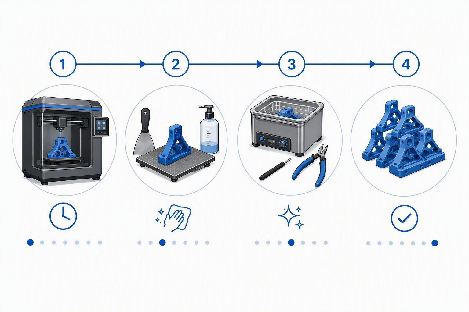
Post-processing and assembly. Support removal, sanding, threading, and inspection can rival print time. A long print easily produces hours of finishing work.
Failed prints and maintenance downtime. Failures and reprints quietly cut usable output. That's why print-farm operators track first-pass yield — prints that pass QC on the first attempt divided by total prints — when planning small-batch production.
A Simple Framework for How to Calculate 3D Printer Throughput
You don't need a twenty-row spreadsheet. Start with one idea:
Practical throughput = Successful finished parts ÷ Total elapsed production time
Count every minute spent toward finished parts. Total elapsed production time includes printing, setup and plate prep, post-processing, inspection, failed reprints, and related downtime — not just the slice time shown on screen. A practical estimate then accounts for five things:
- Successful parts — those that pass inspection, not every part you started
- Total elapsed production time — from setup to the finished part
- Setup and preparation — slicing, loading, plate prep
- Post-processing time — supports, finishing, inspection, assembly
- Expected failure or reprint rate — how often you must redo a print
Divide the good parts by the sum of that time. There is no universal formula because every part, material, and machine differs, so treat this as a way to make your estimate transparent and testable — not a guaranteed number.
⚠️ Warning: Skipping post-processing and failures is the most common way small-batch runs fall behind.
Comparing Production Workflows for 3D Printing Batch Production
How you arrange work changes output as much as speed.
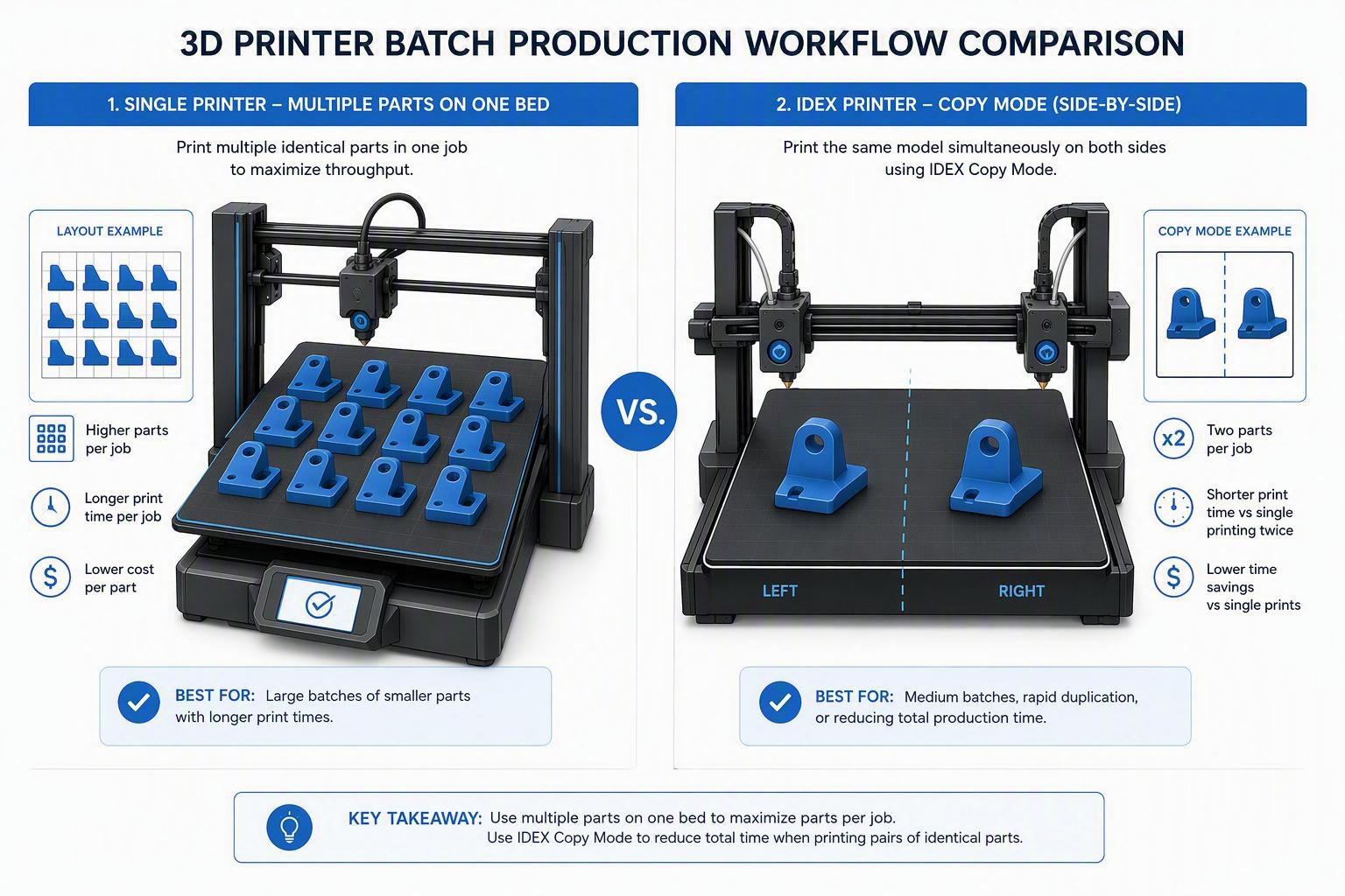
One part at a time. Simplest and easiest to validate. Fresh setup each run, but a failure only costs that one part.
Multiple identical parts on one plate. Shares setup and travel to cut per-part time. Trade-off: one adhesion or layer failure can waste the whole plate.
Copy Mode (IDEX duplication). On an IDEX machine, Copy Mode runs two identical parts side by side across divided halves of the X-axis. It can reduce wall-clock time when two identical parts fit within the divided working area, but actual savings depend on geometry, motion, tool changes, and print settings.
Mirror Mode. Mirror Mode creates a mirrored pair using coordinated toolhead motion. It is useful for left- and right-hand parts, but it does not enlarge the printable area.
Neither Copy nor Mirror doubles output automatically; both still need a geometry that fits a divided bed and solid calibration.
Running multiple printers. More machines add output, but also downtime, maintenance, and queue complexity — they only help if standardization and first-pass yield keep pace.
A larger-format printer. A bigger plate holds more small parts or one large part, but it won't print a single detailed part faster.
Using Slicer Estimates and a Practical Workflow to Plan Output
Slicers estimate print time and material before you start — good for rough planning, but not a guarantee. Results can differ with firmware, acceleration limits, tool changes, and settings, so use the estimate to compare arrangements (one-per-plate versus several), then correct it against real runs. Our guide to reading the slicer preview explains what the time estimate actually reflects.
To build a trustable figure:
- Choose a representative model — one typical of your real jobs, not your easiest part.
- Slice it with your intended settings — the same layer height, infill, and speeds.
- Record the estimated print time and material from the slicer.
- Add setup and post-processing time.
- Run a small test batch under production-like conditions.
- Record successful and failed parts, including why failures happened.
- Update your estimate with the measured time, output, and failure rate.
A Small-Batch Example: How the Estimate Shifts
Note: All numbers below are illustrative examples only. Your results depend on the printer, model, material, and settings.
Say you need 40 usable copies of a small bracket.
One part per plate. If one bracket takes 1 hour (illustrative), 40 parts run in about 40 print hours plus setup between runs — simple but slow.
Several on one plate. If four brackets print together in 2.5 hours (illustrative), ten plates take about 25 print hours because setup is shared. But if one plate warps and all four fail, add a reprint plate (another 2.5 hours).
Mirrored pair. If the job needs a left-and-right pair, a mirrored run of about 2 hours (illustrative) handles both in one pass — useful only because you genuinely need mirrored parts.
Added post-processing. Ten minutes of finishing per part (illustrative) adds roughly 6.7 hours of manual work to any 40-part scenario.
Each workflow shifts print hours, setup, risk, and finishing differently — none is always best.
How DualX IDEX and Its Print Modes Can Fit Into Planning
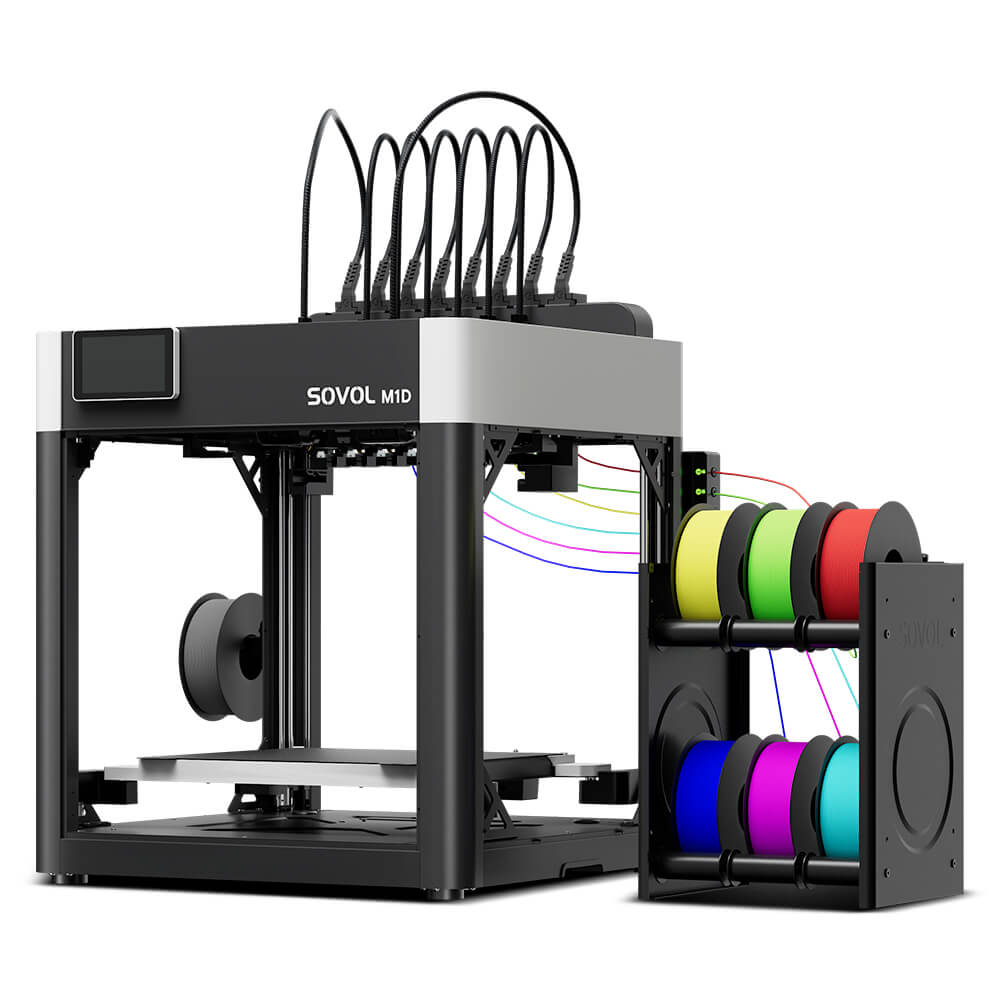
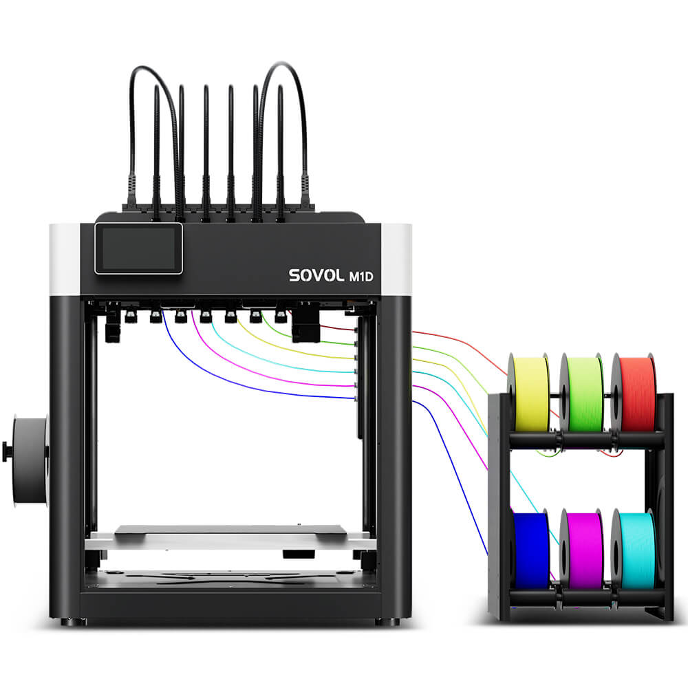
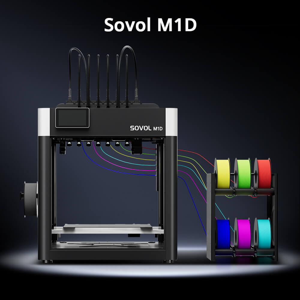
As one example of this hardware, the Sovol M1D pairs its DualX independent dual-extruder (IDEX) tool-changing system with Single, Multi, Copy, and Mirror modes.
What matters for 3D printer productivity is how each mode changes your layout and planning:
- Single and Multi modes vary in build area: single-nozzle printing is listed at up to 300 × 300 × 350 mm, while Dual-Head, Copy, and Mirror modes use different usable areas. Check the selected mode in the slicer preview before planning a batch (per the official product specifications). Multi still assigns independent toolheads to different colors, materials, or supports in one job — handy for multi-material functional parts, though tool changes and purging add time.
- Copy and Mirror modes run both toolheads across divided halves of the X-axis for two identical parts or a mirrored pair at once, shortening wall-clock time when the geometry fits.
- The tool-changing design and six-channel filament system handle loading and switching, reducing the babysitting a multi-material job normally needs.
None of this makes the M1D "the fastest" or guarantees a part count — your model, settings, and workflow still decide throughput.
Choosing a Workflow Based on the Job
- Prototypes — one at a time; low risk, easy to iterate.
- Small batches of identical parts — pack a plate with copies to share setup time.
- Identical replacement parts — multiple-per-plate or Copy Mode when the geometry fits a divided bed.
- Mirrored components — Mirror Mode, because you need two opposite parts.
- Multi-color products — Multi Mode or tool changing, expecting purging overhead.
- Multi-material functional parts — Multi Mode pairing structural and flexible or support materials, planned around compatibility.
- Print-farm production — batch by material and risk, standardize profiles, check tolerances, and track first-pass yield before scaling.
When fits must be right, budget for realistic 3D printing tolerances so parts measure up consistently.
Common Mistakes When Estimating 3D Printer Throughput
- Treating maximum speed as the only metric — real output depends on the workflow, not the mm/s rating.
- Ignoring failed prints and reprints — gross prints aren't usable output.
- Skipping tool-change and post-processing time — purging, loading, and finishing add up as much as printing.
- Basing estimates on a tiny test model — a fast little part flatters the whole batch.
- Assuming every model suits Copy or Mirror Mode — divided-bed modes need geometry that fits.
- Comparing printers across different layer heights or infill — that compares settings, not machines.
A Practical Checklist for Estimating 3D Printer Throughput
- Pick a representative model and your production settings
- Pull slicer estimates for time and material, then add setup and plate-prep per run
- Account for failures, reprints, and post-processing per part
- Sum to total elapsed batch time and divide usable parts by it
- Run a test batch and update your figure with real results
FAQ
Does higher print speed always mean more parts per day? No. Speed only helps if the hotend, cooling, and geometry sustain it. Daily output is set by the whole workflow — setup, failures, post-processing, and uptime.
Does printing more parts on one plate always improve productivity? Usually, because setup is shared — but one warped part can waste the whole plate, so several smaller sequential runs are sometimes safer.
Does Copy Mode or Mirror Mode double my output? Only when conditions line up. Both split the bed into halves, so each part must fit its half, and neither enlarges the printable area.
How much extra time should post-processing take? Support removal, finishing, and assembly can range from minutes to hours per part — measure your own parts rather than guessing.
Conclusion
Real 3D printing throughput isn't what the spec sheet promises. It's the number of usable, finished parts you produce over total elapsed time, after setup, failures, tool changes, and post-processing. Advertised speed only describes how fast the toolhead can theoretically move.
Build your estimate from measurements on a representative model, then correct it after a test batch. Measure the whole workflow rather than trusting a spec number — and you'll quote delivery times and plan batches you can actually hit, because real throughput is measured in good parts per hour, not millimeters per second.