




However, many makers and engineers experience frustration when their first printed gear set fails immediately. Either the gear teeth bind tightly together and refuse to turn, or the teeth strip clean off the hub under moderate motor torque. These failures rarely stem from printer quality alone. Instead, they usually happen because standard CAD gear generators assume zero-tolerance manufacturing, while FDM extruders push molten thermoplastic that expands slightly in the XY plane.
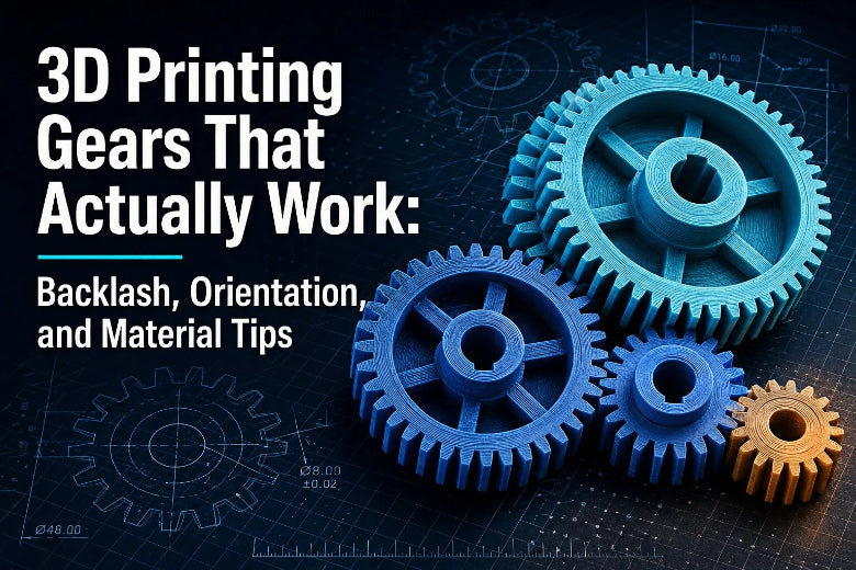
In this comprehensive guide on how to 3D print gears, we will break down the exact engineering parameters required for 3D printing gears that run smoothly, transmit power reliably, and resist premature wear. We will cover critical geometry rules like backlash allowance and module selection, print orientation trade-offs, slicer perimeter tuning, and material choices between PLA, PETG, and ASA.
Why 3D-Printed Gears Fail
Before diving into CAD parameters, it helps to understand why 3D-printed gears lock up or break in the first place. FDM 3D printing introduces physical constraints that standard mechanical design software does not account for automatically.
- Dimensional Over-Extrusion and Expansion: FDM nozzles deposit molten plastic paths that slightly bulge outward. When two theoretical gear profiles meshed in CAD are printed with zero backlash, this microscopic perimeter expansion causes the tooth flanks to press firmly against each other, creating massive friction or total binding.
- First-Layer "Elephant’s Foot": The initial layers printed against a heated build plate are squeezed slightly outward to ensure bed adhesion. On a gear, this creates a widened flange at the bottom of every tooth that wedges into the mating gear's root.
- Tooth Root Shear (Stress Risers): In involute gearing, the narrowest point of the tooth is at its root where it connects to the gear body. If the CAD model uses sharp internal corners without root fillets, cyclic bending loads create severe stress concentration, snapping teeth off along layer lines.
- Frictional Heat and Surface Roughness: The layer-by-layer step structure of an FDM surface acts like a fine file against meshing teeth. At higher rotational speeds, unlubricated layer lines generate frictional heat. Because thermoplastics have low thermal conductivity, heat accumulates quickly in the teeth until the material softens and deforms.
Important Gear Design Terms: Tooth Count, Pitch, and Backlash
To design reliable 3D printed gears, you do not need a degree in mechanical engineering, but you must understand a few core geometric relationships.
Module (m)
In metric gear design, Module (m) defines the physical size of the gear teeth. It is calculated by dividing the pitch diameter (Dₚ) in millimeters by the total number of teeth (Z):
Module (m) = Pitch Diameter (Dₚ)/Number of Teeth (Z)
A larger module means larger, thicker gear teeth. For standard FDM printing with a 0.4 mm nozzle, Module 1.5 to 2.0 is the ideal sweet spot.
Pitch Diameter (Dₚ)
The pitch diameter is the diameter of an imaginary pitch circle where two meshing gears make theoretical rolling contact. When calculating the center-to-center mounting distance (C) for two spur gears, the formula is:
C = (Dₚ1 + Dₚ2) / 2 = m × (Z₁ + Z₂) / 2
3D Printed Gear Backlash
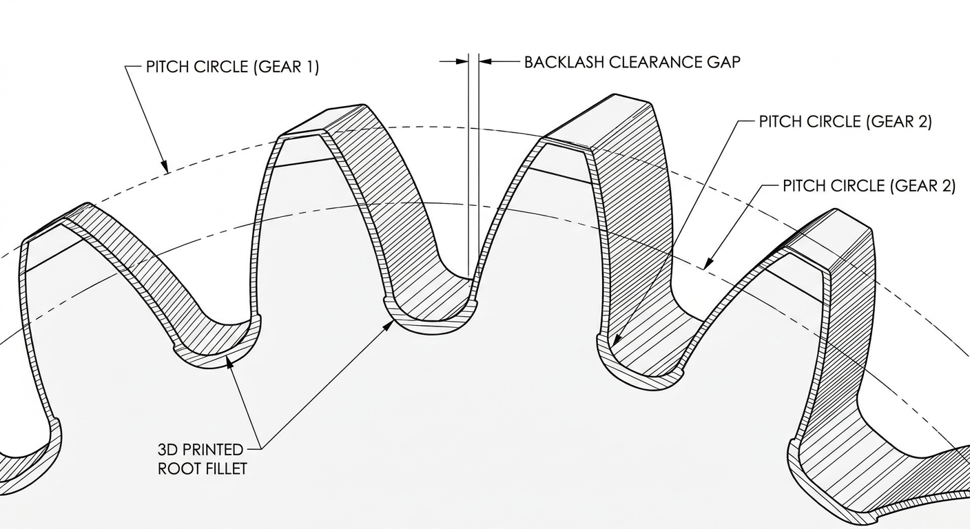
Backlash is the intentional clearance gap between the non-driving flanks of meshing gear teeth. In industrial metal machining, backlash prevents binding due to thermal expansion. In FDM printing, backlash is mandatory to absorb printer tolerances, filament variance, and perimeter expansion.
Pressure Angle
The pressure angle determines the shape of the tooth involute flank. Standard industrial gears use a 20° pressure angle. While 20° works well for 3D printing, increasing the pressure angle to 25° widens the tooth root, giving the tooth greater shear strength under heavy loads.
Minimum Tooth Count
To prevent "undercutting"—a condition where the cutting tool or CAD generator carves away material at the tooth root, weakening it—spur gears with a 20° pressure angle should generally have no fewer than 12 to 14 teeth.
How to Design Gears for FDM Printing (FDM Gear Design Rules)
When creating custom gear profiles in CAD software (such as Fusion 360, FreeCAD, or SolidWorks), apply these practical design rules tailored for FDM printing.
Important: The geometric parameters, backlash allowances, and slicer settings outlined below are practical baseline starting points rather than rigid universal rules. Real-world gear performance and tolerances depend on gear diameter, tooth count, torque load, filament choice, nozzle diameter, and individual printer calibration. Always validate your specific configuration with a quick test print.
1. Select the Right Tooth Size (Module) for Your Nozzle
While SLA resin printers can resolve fine Module 0.5 teeth, standard FDM nozzles (0.4 mm) struggle with modules below 1.0.
- Module 1.5–2.0 (Common Baseline): Often provides sufficient thickness for continuous wall perimeters across the tooth profile. Teeth are generally robust and tolerant of minor printer wobble.
- Module 1.0 (Practical Lower Range): Can work well for light-duty mechanisms, provided the extruder is well-calibrated and extrusion multipliers are fine-tuned.
- Module < 1.0 (Higher Precision Challenge): Teeth become narrower than standard extrusion passes, which can round off involute profiles unless using smaller nozzles or fine-tuned SLA setups.
2. Add Generous Root Fillets
Never leave sharp 90° inside corners where the tooth flank meets the root circle. Add a fillet radius equal to 0.3 to 0.5 times the module (0.3–0.5 × m). Radiused roots distribute bending stress across a larger area, dramatically increasing resistance to tooth shear.
3. Incorporate Backlash Directly into CAD Geometry
Instead of trying to position gear shafts slightly further apart on your assembly frame, build backlash directly into the gear tooth profile. You can achieve this in CAD by offsetting the tooth flank faces inward by 0.1 mm to 0.2 mm per gear, creating a total meshing clearance of 0.2 mm to 0.4 mm.
4. Reinforce Hubs, Bores, and Face Width
The gear face width (thickness) should generally be at least 3 to 5 times the circular pitch. Thin gears tilt on their shafts, concentrating loads on the tooth edges.
For shaft mounting:
- Avoid relying on a simple press fit over a smooth printed bore; plastic creeps under stress and will loosen over time.
- Use D-shaped shafts, square drives, metal keyways, or heat-set threaded inserts with setscrews to transmit torque securely from the shaft to the gear hub.
Print Orientation and Layer Direction
The orientation in which you place a gear on the build plate creates a fundamental trade-off between dimensional profile accuracy and mechanical layer strength.
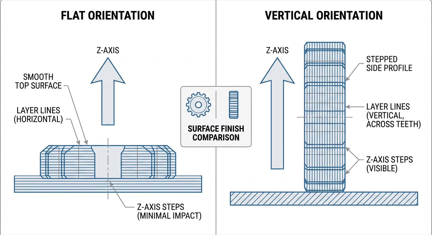
Printing a standard spur gear flat on the build plate is often a good starting point when tooth-profile accuracy is the priority. However, the optimal orientation still depends on the primary load direction, gear face width, support requirements, and intended service conditions.
Flat Orientation (Shaft Axis Parallel to Z-Axis)
Placing the gear flat on the print bed is a common baseline orientation for desktop spur gears.
- Advantages: The printer draws the gear's involute tooth profile entirely within the XY plane. Linear rails and CoreXY motion systems excel at precise XY positioning, resulting in smooth pitch profiles and helping produce a more consistent bore.
- Trade-Off: Bending forces exerted on the gear teeth act parallel to the printed layer lines. Under severe shock loads, teeth may shear along a layer interface.
Vertical Orientation (Shaft Axis Parallel to XY-Plane)
Attempting to print a spur gear standing vertically on its edge changes the direction of layer lines.
- Advantages: Layer lines run along the length of the tooth face, which can increase bending strength along the tooth root in specific load orientations.
- Disadvantages: The gear profile is formed by stepped Z-axis layers, creating rougher tooth flanks. Shaft bores require support or post-processing, and support removal can degrade tooth surface finish.
Key Takeaway: Printing flat is generally recommended for tooth accuracy, but high-load custom gears should be evaluated holistically. Rather than sacrificing profile accuracy with awkward orientations, mechanical strength is typically enhanced by increasing perimeter wall counts, optimizing layer bonding, and adding generous CAD root fillets.
Recommended Slicer Settings for Functional Gears
Slicing settings play a huge role in determining whether a 3D-printed gear operates quietly or breaks under load. Generic slicer profiles intended for decorative models are inadequate for functional mechanical parts.
1. Wall Count (Perimeters) Over Infill Percentage
When a gear tooth experiences load, stress is concentrated on the outer perimeter shell, not the sparse internal infill.
- Set your slicer to 4 to 6 solid walls (perimeters).
- For standard Module 1.5 gears, 5 walls will make the teeth almost entirely solid plastic formed by continuous concentric extrusion paths.
- Internal hub infill should be set to 40% to 50% Gyroid or Grid pattern to prevent hub flex.
2. Layer Height Selection
Use a layer height between 0.16 mm and 0.20 mm for a standard 0.4 mm nozzle. While thicker layers (like 0.28 mm) print faster, thinner layer heights yield a smoother slope transition along the involute flank, reducing running friction and gear noise.
3. Seam Placement (Avoid Active Tooth Flanks)
The "Z-seam" is the spot where the nozzle starts and ends each outer perimeter loop, leaving a small plastic blob. If your slicer places Z-seams on the meshing face of gear teeth, every revolution will produce a noticeable bump and binding point.
- Set Z-Seam Alignment to Random, or manually paint the seam placement on the internal hub or non-meshing gear faces away from the teeth.
- Enable Scarf Joint Seams if your slicer (such as OrcaSlicer or PrusaSlicer) supports it to smooth out perimeter start points.
4. First-Layer Elephant’s Foot Compensation
To prevent the first layer from flaring outward and causing bottom-edge binding:
- Set Elephant's Foot Compensation (or
Initial Layer Horizontal Expansion) in your slicer to -0.15 mm to -0.20 mm. - Alternatively, add a small 0.5 mm × 45° chamfer to the bottom edge of your gear model in CAD.
Pro Tip: Keeping outer perimeter print speeds moderate (e.g., 30–50 mm/s as a baseline starting guideline) helps prevent corner overshoot on small tooth contours. While high-performance CoreXY machines like the Sovol SV08 can help maintain repeatable motion at higher accelerations, tuning outer perimeters conservatively is a reliable way to ensure smooth tooth flanks.
PLA vs. PETG vs. ASA: Choosing the Best Filament for Gears
Choosing the right filament is critical for matching your gear set to its working environment. No single plastic is superior in all conditions; each has distinct mechanical trade-offs and requires practical validation.
Filament Property Comparison Matrix
|
Material |
Typical Tensile Strength |
Typical Tg — varies by formulation; not a continuous-use temperature |
Impact Toughness |
Friction & Wear |
Best Applications |
|---|---|---|---|---|---|
|
PLA |
Very High (~50–65 MPa) |
Low (~55–60°C) |
Low (Brittle) |
Moderate (Heats under high RPM) |
Low-speed prototypes, light static loads, high detail |
|
PETG |
Moderate (~40–50 MPa) |
Moderate (~75–80°C) |
High (Ductile) |
Moderate-Low (Durable running) |
Moderate functional gearboxes, general prototyping |
|
ASA |
Moderate-High (~40–55 MPa) |
High (~95–100°C) |
High (Shock resistant) |
Moderate-Low |
Outdoor machinery, enclosed motor drives, high-temp |
1. PLA (Polylactic Acid)
- Pros: PLA offers high tensile strength and stiffness among commodity filaments. It prints with minimal thermal shrinkage, producing crisp, accurate tooth geometry.
- Cons: PLA has a low glass transition temperature (Tg ≈ 55–60°C). Continuous mesh friction can generate local heat that softens PLA teeth, leading to accelerated wear. It is also more brittle under shock loads.
- Verdict: Suitable for low-speed gearing, display models, and initial dimensional fit testing.
2. PETG (Polyethylene Terephthalate Glycol)
- Pros: PETG offers good ductility and impact resistance compared to standard PLA. Teeth deform elastically under moderate shock loads rather than snapping abruptly. Its higher temperature resistance (75–80°C) makes it a practical option for loaded functional mechanisms. For detailed slicing advice, consult Sovol's essential PETG print settings guide.
- Cons: PETG is slightly more flexible than PLA, meaning thin teeth may flex under heavy torque. Stringing can leave fine wisps between teeth that require heat-gun cleanup.
- Verdict: May be a good choice for functional gear mechanisms requiring higher impact tolerance, though wear testing under load remains essential.
3. ASA (Acrylonitrile Styrene Acrylate)
- Pros: ASA is an engineering-grade thermoplastic with high thermal resistance (95–100°C), good impact strength, and exceptional UV resistance. It stands up to hot motor mounts and outdoor exposure without degrading. If your design operates near hot stepper motors, review Sovol's guide to high-temperature filaments for functional parts and their ASA vs PETG outdoor comparison guide.
- Cons: ASA shrinks as it cools, making it prone to warping on un-enclosed printers. Printing small gear teeth cleanly requires precise thermal management.
- Verdict: Can be a suitable option for higher-temperature gear enclosures and outdoor setups, provided warp control is properly managed.
How to Make a Gear Calibration Test
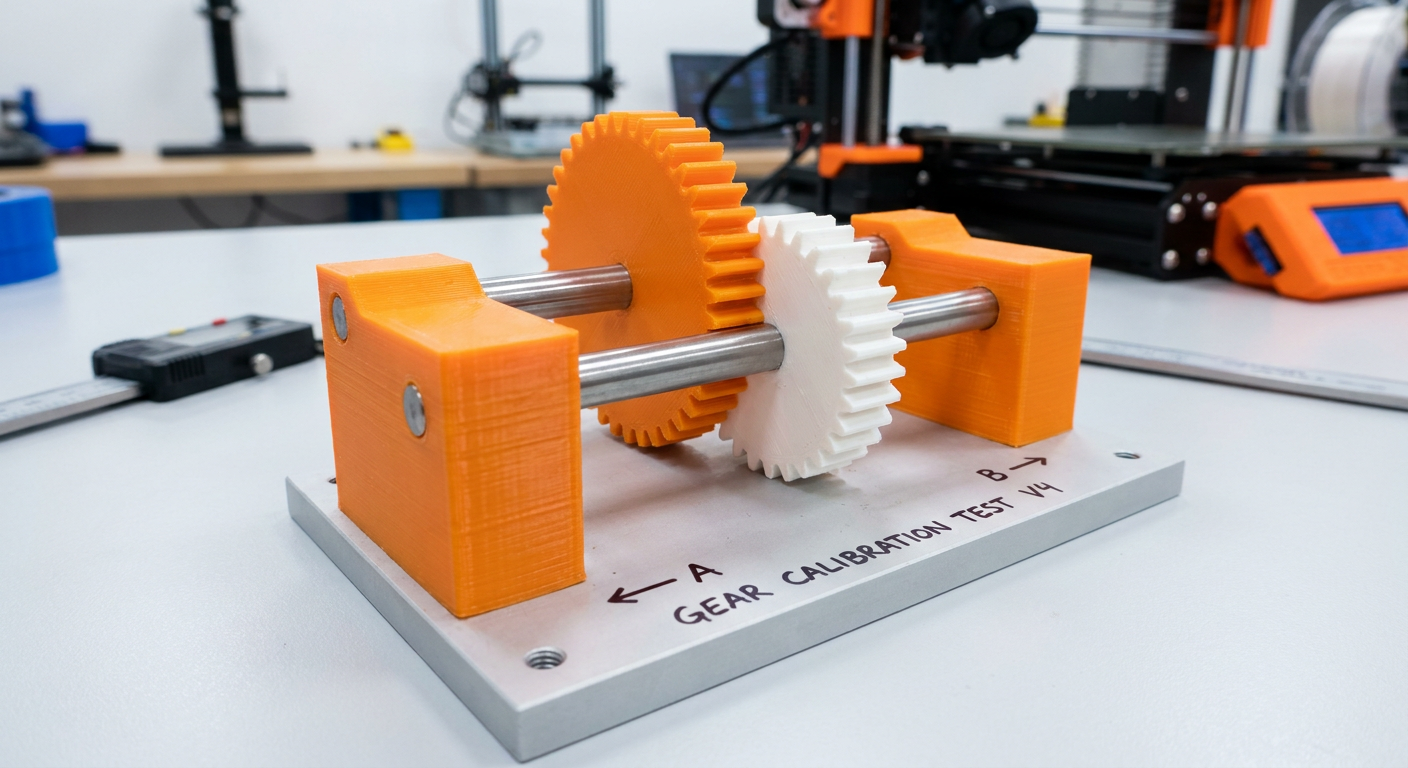
Never print a full complex gear assembly without verifying your printer's specific tolerance and backlash behavior first. Use a systematic test workflow to save filament and tuning time.
Systematic Calibration Workflow
- Design a Calibration Rig: In CAD, model a rigid base plate with two fixed vertical pins separated by a precise center distance (e.g., C = 30.0 mm).
- Model Test Pairs with Controlled Variances: Prepare simple spur gear pairs (e.g., 15-tooth Module 2.0). Change only one variable at a time—such as testing CAD tooth face offset values systematically—rather than adjusting CAD geometry and slicer settings simultaneously.
- Print Under Production Conditions: Print test components using the exact filament, wall perimeter count, and layer height planned for the final assembly.
- Evaluate Mechanical Fit: Slide test gears onto the base pins and evaluate rotational feel:
- Binding or Hard Catching: Indicates over-extrusion or insufficient backlash allowance. Increase CAD tooth clearance incrementally, or adjust your slicer's dimensional compensation (note that parameter names and positive/negative direction signs vary between OrcaSlicer, PrusaSlicer, and Cura).
- Excessive Rotational Slop: Indicates oversized clearance gaps. Reduce CAD tooth offset in small steps.
- Smooth Rolling Fit: Gears spin freely without binding, maintaining minimal necessary play for continuous rotation.
Common Problems: Skipping, Binding, Noise, and Tooth Wear
Even with careful design, real-world printing variables can cause operational issues. Here is how to diagnose and fix the most common 3D-printed gear problems.
1. Teeth Binding or Sticking
- Cause: Over-extrusion, insufficient backlash allowance, zero elephant's foot compensation, or Z-seam blobs on tooth flanks.
- Fix: Decrease slicer extrusion multiplier incrementally, adjust initial layer horizontal expansion compensation in small steps, and paint Z-seams away from meshing faces.
2. Teeth Stripping or Shearing at the Root
- Cause: Sharp 90° root corners (stress risers), low wall count (relying on sparse infill), or brittle material choice under shock load.
- Fix: Add generous root fillets in CAD, increase wall perimeter counts step-by-step, and consider switching to more ductile filaments like PETG or ASA.
3. Excessive Gear Noise and Vibration
- Cause: Stepped layer lines acting like files, misaligned shaft center distances, or printing with very thick layer heights.
- Fix: Reduce layer height gradually for smoother flank transitions, test a compatible plastic grease, and run the gear pair under light load for a brief break-in period.
4. Tooth Deformation Over Time (Thermal Softening)
- Cause: High rotational speeds generating frictional heat beyond the material's glass transition temperature (Tg).
- Fix: Test a compatible plastic lubricant, lower rotational RPM, or upgrade from PLA to higher Tg filaments like PETG or ASA.
When to Use 3D-Printed Gears vs. Metal Gears
While 3D-printed gears excel in custom prototypes and medium-duty automation, engineering honesty requires recognizing their physical limits.
⚠️ Warning: Never use 3D-printed thermoplastic gears in safety-critical systems, high-torque industrial drivetrains, or applications where gear failure could cause physical injury or property damage.
Ideal Use Cases for 3D-Printed Gears
- Low to medium torque mechanisms (robotics arms, automated blinds, camera sliders, workshop jigs).
- Custom reduction ratios where commercial stock gears are unavailable or cost-prohibitive.
- Prototyping and validating gearbox packaging before ordering CNC-machined metal gears.
- Sacrificial "safety links" designed to break cleanly before a costly motor burns out.
When to Upgrade to Machined Metal Gears
- Continuous high-RPM applications where frictional heat generation exceeds thermoplastic thermal dissipation limits.
- Heavy structural loads requiring narrow gear faces or high power density.
- Precision positioning drives requiring near-zero backlash (such as CNC axis drives), where plastic teeth flex under load.
Final Gear Printing Checklist
Before sending your next gear design to your 3D printer, verify these ten crucial points:
- Module Size Checked: Module is 1.5 or larger for standard 0.4 mm nozzles (or ≥ 1.0 for fine-tuned setups).
- Minimum Tooth Count: Gear has at least 12–14 teeth to prevent root undercutting.
- Root Fillets Included: CAD model has 0.3–0.5 × m radius fillets at internal tooth roots.
- Backlash Built In: Flanks have 0.1–0.2 mm offset per gear (0.2–0.4 mm total clearance).
- Flat Print Orientation: Gear is placed flat on the build plate with shaft axis aligned along the Z-axis.
- Wall Count Maximized: Slicer set to 4 to 6 solid walls so teeth are solid perimeter paths.
- Layer Height Optimized: Sliced at 0.16 mm – 0.20 mm for smooth flank slope transitions.
- Z-Seam Relocated: Seam placement set to Random or painted away from meshing tooth faces.
- Elephant's Foot Compensated: Initial layer horizontal expansion reduced by -0.15 mm to -0.20 mm.
- Appropriate Filament Selected: PETG or ASA evaluated for loaded/high-temp drives, with PLA reserved for low-speed prototypes and dimensional checks.
By applying these practical design rules and slicer settings, you can reliably produce custom FDM gear assemblies that mesh smoothly, carry mechanical loads, and stand up to demanding workshop projects.
Frequently Asked Questions (FAQ)
What module size works best for 3D printed spur gears on a 0.4 mm nozzle?
For standard FDM printers equipped with a 0.4 mm nozzle, Module 1.5 to 2.0 provides an optimal baseline. Teeth in this size range are sufficiently thick to allow 4 to 6 solid wall perimeters, ensuring high mechanical strength and good printing reliability. While Module 1.0 is achievable with well-calibrated extrusion, smaller modules often lead to rounded tooth profiles and binding.
Should I apply lubricant to 3D printed thermoplastic gears?
A plastic-compatible lubricant may reduce friction and noise, but compatibility depends on the filament and lubricant. Check the lubricant's material guidance and test a small gear pair first. Lubrication cannot compensate for incorrect backlash, alignment, or poor surface quality.
Why do 3D printed gear teeth frequently snap off at the root?
Tooth shear at the root is typically caused by sharp 90° internal corners that act as severe stress concentration points, low perimeter counts relying on sparse infill, or printing brittle filaments under shock load. Adding generous root fillets in CAD and increasing slicer wall counts distributes bending loads and improves tooth durability.
Can herringbone or helical gears be 3D printed to reduce operational noise?
Helical and herringbone gears can reduce noise or improve load sharing, but they are more complex to print and align. They still require adequate clearance, support, and test fitting before being used in a loaded mechanism.
How much backlash should I build into my CAD gear model?
A total meshing backlash clearance of 0.2 mm to 0.4 mm (achieved by offsetting tooth flank faces inward by 0.1 mm to 0.2 mm per gear) serves as an ideal initial starting point for desktop FDM printers. This gap absorbs slight over-extrusion, thermal expansion, and microscopic surface roughness.