



Three things make small figures hard for a filament printer. The nozzle lays down a bead of finite width, so features narrower than the effective extrusion width may disappear or merge, depending on the slicer and line-width settings. Layers stack in visible steps, which is why slanted surfaces show a staircase texture. And supports have to touch the model somewhere, usually on the back or under the arms, leaving marks that are hard to sand off a 28 mm figure. Resin printers can preserve smaller details in some cases, but they still require supports and post-processing, so treat FDM as a capable but limited tool for this job. The rest of this guide covers model choice, nozzle and layer trade-offs, orientation, supports, slicer checks, bases, and a short test-print loop you can run before committing to a full figure.
The Quick Answer: What Actually Controls Detail on FDM Miniatures
Detail retention on a miniature is the product of several interacting choices, not one magic setting. A fine nozzle with a careless orientation and heavy automatic supports will still produce a blurry, scarred figure. The table below shows what each factor actually controls and a reasonable place to start testing.
|
Factor |
What it controls |
What to try first |
|---|---|---|
|
Model design and scale |
Whether a feature is wide enough to survive slicing at all |
Pick models built for FDM or scale up slightly; thicken the thinnest parts |
|
Nozzle size |
Smallest reliable bead, and therefore horizontal detail |
Test a finer nozzle on a small model rather than assuming a size |
|
Layer height |
Vertical smoothness, staircase effect, and print time |
Lower it one step and compare on a test piece |
|
Orientation |
Which surfaces are smooth, where layer lines land, how much support is needed |
Tilt the figure back so the face points up and away from supports |
|
Supports |
Whether overhangs print at all, and how clean the contact surfaces are |
Tree/organic supports with painted blockers over the face and chest |
|
Slicer preview |
Whether the toolpath actually contains the detail you expect |
Inspect layer by layer before every new model |
A smaller nozzle or lower layer height may help preserve fine details, but the best combination depends on the printer, nozzle, material, slicer profile, and model geometry. Test the result on a small model before printing the final miniature.
Which Miniature Features FDM Handles Well — and Which It Struggles With
It helps to separate the two axes of detail before judging any feature. Prusa's nozzle guide explains that nozzle diameter affects detail almost exclusively in the horizontal plane, while layer height governs vertical and slanted surfaces. A feature that runs sideways across the print is limited by bead width; a feature that rises vertically is limited by layer stepping. Most miniature problems come from one of those two limits, plus support contact.
Faces and facial features are where FDM miniatures are won and lost. Eye sockets, nose bridges, and lips are shallow and small, so a gap or relief narrower than the extruded bead gets merged into its neighbor or dropped by the slicer. On slanted cheeks and foreheads, layer stepping adds visible banding right where the eye goes first. In practice, FDM can hold a nose, a brow ridge, and a suggestion of an eye socket; pupils, individual teeth, and fine wrinkles are where it realistically stops, and resin remains the better tool for that smallest work. Support contact on the face makes it worse, which is why many painters orient the front away from supports.
Thin weapons and accessories — swords, spears, bows, slender staffs — are the classic casualties. A cross-section narrower than the bead may print as a single fragile line or disappear when the slicer cannot place a wall there, and these are also the parts most likely to snap during support removal.
Hair, fur, and surface texture are the least FDM-friendly features, because bead width smooths fine strands and shallow grooves while layer stepping competes with them. Chunky hair masses, swept locks, and bold, deep texture read far better than individual strands.
Armor details are generally the friendliest category. Broad plates, pauldrons, and shield faces give flat, upward-facing surfaces where nozzle diameter sets the detail, and raised rims and edges come through cleanly. Rivets and trim lines still need enough width to survive slicing, and a raised detail on an upward-facing surface is easier than a recessed groove of the same size.
Small gaps and separate parts are the last group. A gap narrower than the effective line width often fills in or bridges shut, so an arm held slightly away from the torso can fuse into it; separate parts need real clearance, and tiny components often print better laid flat than standing as thin towers.
Choosing or Modifying a Miniature Model for FDM
Model choice does more for your results than any slicer tweak, because a feature that is too thin to slice cannot be rescued afterward. Treat the points below as a screening checklist rather than hard rules — the right call depends on the geometry in front of you.
- Start with the model and the scale. A clean, well-modeled figure slices better than a repaired mesh, and printing a little larger gives every feature more beads to work with.
- Compare feature width with line width. Where possible, size weapons, ankles, and raised trim as multiples of your slicer's line width so the slicer can fit whole passes; Sovol's thin-wall guide explains why non-integer wall thickness can leave gaps or missing toolpaths. Preview the sliced result rather than trusting the CAD number alone.
- Modify only what the print needs. Thicken the thinnest weapons and ankles, add chamfers or fillets where a sharp step is likely to curl or break, split a fussy figure into separate parts, and flatten or key contact surfaces so glued joints sit straight.
Nozzle Diameter and Layer Height: A Trade-Off, Not a Formula
These are two independent variables, and pushing either one to its extreme costs you something else. Nozzle diameter sets the smallest bead you can lay down reliably, so it governs horizontal detail. Layer height sets vertical smoothness and, just as importantly, print time. Prusa's knowledge base explains that layer height drives vertical resolution while nozzle diameter drives XY detail, and both have to be tuned to your own profile. A smaller nozzle or lower layer height may help preserve fine details, but the best combination depends on the printer, nozzle, material, slicer profile, and model geometry. Test the result on a small model before printing the final miniature.
Orientation: Where the Face Points and Where the Layers Run
Orientation is the highest-leverage decision you make in the slicer, because it changes four things at once: which surfaces are visible and smooth, where layer lines show, how much support the model needs, and how loads run relative to the layer boundaries. Get it right and a mediocre profile can produce a clean figure; get it wrong and no amount of tuning will fix the face.
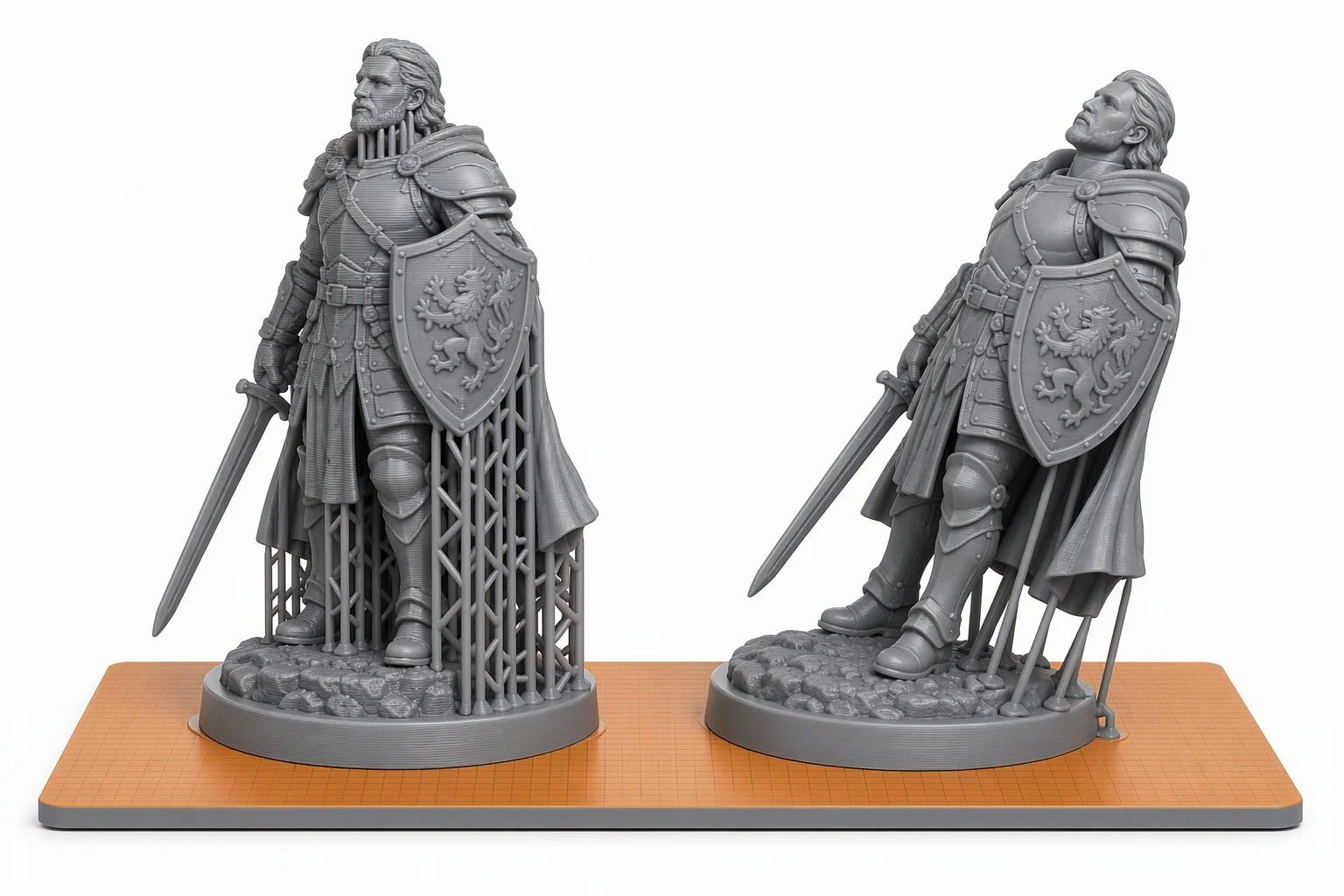
Tilting the figure backward so the face looks up and away from the plate does two things at once: it keeps support contact off the visible front, and it changes the angle at which layer lines cut across the cheeks and brow. An upright figure often prints the face into a stack of near-horizontal terraces; a tilted one spreads those steps over more layers and softens the banding.
Setting Up Supports for Thin Weapons, Arms, and Overhangs
Supports are a common source of miniature print failures, and thin parts are the reason. A support that holds a raised sword steady during printing can snap that sword off during removal, so the goal is the fewest contact points that still keep the overhang anchored.
Start with the support style. Tree or organic supports reach the model with fewer contact points, which can leave less scarring on protruding arms and weapons; a classic pattern such as zigzag can break away in chunks, though it may need more manual cleanup. Neither is automatically better for every figure. Automatic generation often adds more contact than a miniature needs, so paint supports onto the specific overhangs and use blockers over the face, chest, and any surface you want kept clean.
The top Z distance and interface decide how cleanly the support releases. The OrcaSlicer support settings documentation defines Top Z distance as the gap between the top of the support and the overhang above it, and Bottom Z distance as the gap under a support standing on the model; both are rounded to a layer-height multiple unless independent support layer height is enabled. Too small a gap fuses the support to the figure; too large a gap lets the overhang sag. The interface is the dense contact region, so adjust its density and layer count separately from the support base. If supports keep fusing, a slightly larger top Z distance and a less dense interface are common adjustments to test before you change the whole profile. The exact setting name and behavior vary between slicers, so check your own software's documentation rather than assuming these labels transfer.
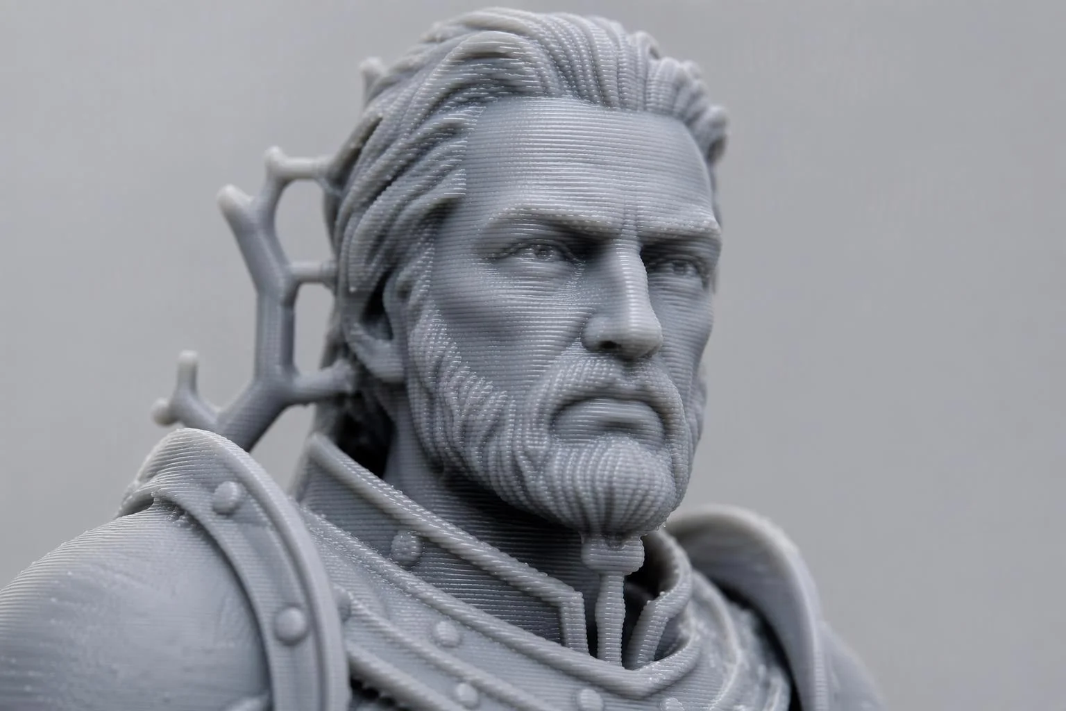
Place contact under a thin weapon or arm rather than on its visible face, and remove it with flush cutters in small pieces instead of pulling. A steeply angled arm may need no support after you rotate the model slightly in the slicer; a nearly horizontal sword usually needs one near the tip. Tiny raised details such as armor trim or hair strands usually do not need support, and blocking them avoids unnecessary scars. Because a narrow limb or support has little bed contact, Sovol's guide to small-part failures lists poor bed adhesion, warping, and cooling problems as common causes, so check plate prep and cooling alongside the support profile. Test any support change on a small piece or a duplicate base before committing a full plate.
Slicer Preview Checks Before You Print
The preview is the cheapest place to catch a failed miniature. A slicer does far more than cut a model into layers — it interprets geometry, applies support decisions, and generates the actual toolpaths — so do not treat a successful slice as a guarantee of a successful print. Scrub through the layers before you commit filament. A practical pre-print check covers five things:
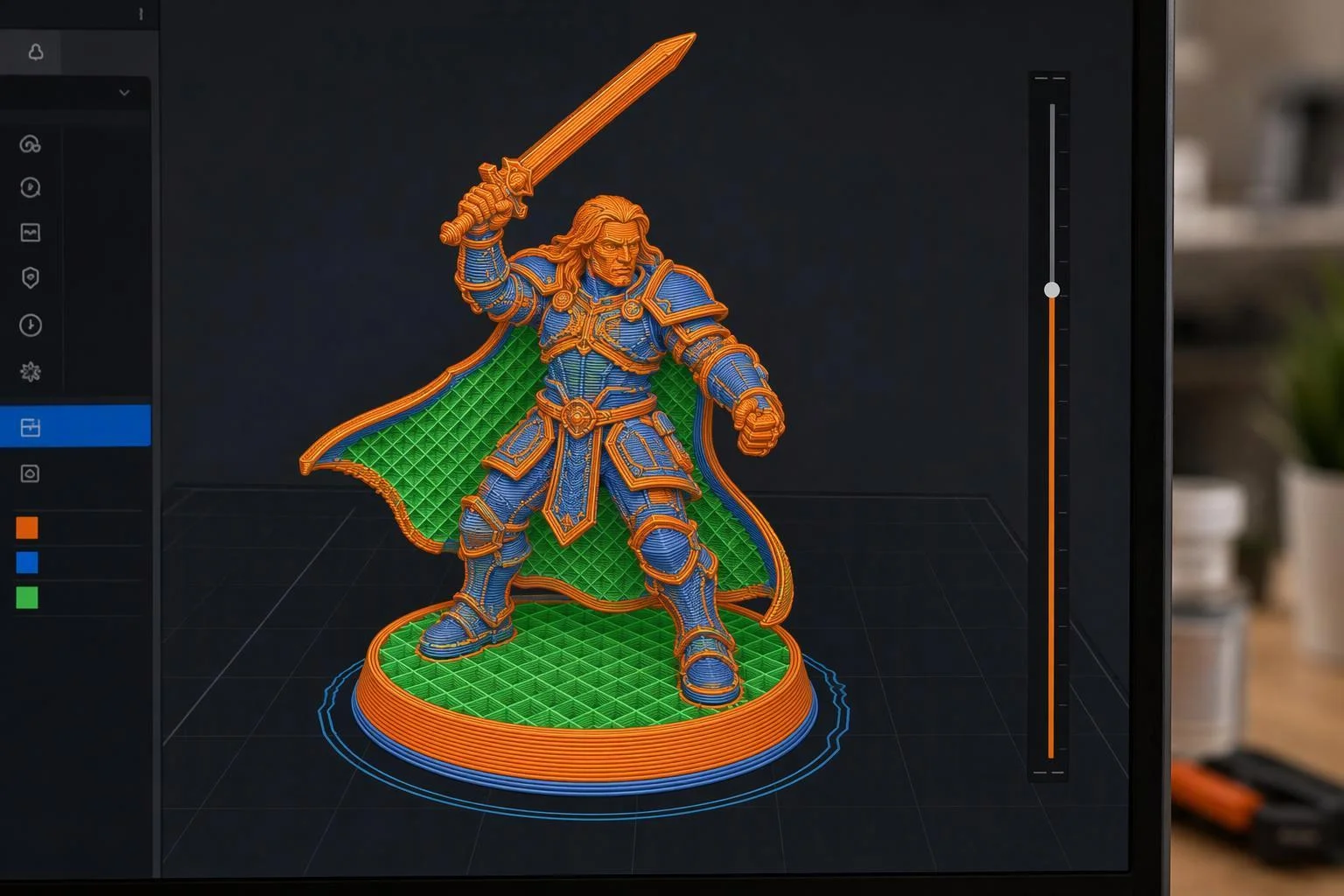
- Missing thin features. Look for weapons, fingers, or trim that vanish from the toolpath. Adjust line width, try thin-wall detection or Arachne if your slicer offers it, or thicken and scale the part in the model.
- Disconnected islands. Look for small areas that start in mid-air with nothing beneath them. Add or reposition supports, or rotate the model so the island is anchored.
- Weak supports. Look for slender support towers, sparse contact under overhangs, or supports that stop short. Add manual supports or change the support pattern or style before printing.
- Small gaps being filled. Look for narrow slots between an arm and body, or between separate parts, that the slicer closes up. Adjust line width slightly within a stable range, change thin-wall settings, or scale or separate the parts so the gap survives.
- Details disappearing between layers. Step through the face and armor layer by layer and watch for a feature that appears for only a layer or two, then merges into its neighbor. Lower layer height, reorient the feature, or thicken it in the model.
Building or Choosing a Stable Base
Base stability is two problems wearing one hat: bed adhesion during printing, and tipping during handling afterward. A top-heavy figure on a small footprint will fall over on the table no matter how well it printed, so settle the base before you settle the settings. For a base you design yourself, make the footprint wide enough that the figure's center of mass stays over it during handling, and check that the bottom is flat and sits fully on the bed. If the base is part of the figure, a small chamfer at the bottom edge or a brim in the slicer can improve bed adhesion, and the figure should be oriented so that footprint prints as a supported first layer. A base printed separately and flat gives a cleaner bottom face and lets you orient the figure freely, at the cost of a glue joint.
A Simple Test-Print Workflow
Printing a full 32 mm figure to discover that the face is mush wastes hours. This loop front-loads the expensive decisions onto a small, fast print.
- Select a small section or test model. Print a bust, a single arm, or a cut-down version of the figure, using the same nozzle, layer height, and orientation you plan for the final print. Verify: the sliced preview shows every feature you expect, with no missing walls.
- Check the face and important details. Inspect the eyes, nose, mouth, and any raised armor trim first, because those areas decide whether the figure reads at arm's length. Verify: you can pick out a nose and eye sockets from normal tabletop viewing distance.
- Evaluate supports and surface quality. Look at where supports touched the model and whether they held the overhangs without scarring the front. Verify: supports released without snapping a thin part, and the contact marks are light enough to sand or paint over.
- Adjust the model or slicer settings. Change one variable at a time — orientation, support placement, line width, or layer height — so you know what fixed the problem. Verify: the change targets the specific defect you saw in step 2 or 3 rather than a guess.
- Print the final miniature. Apply the settings that passed the test and keep the same orientation and support setup. Verify: the finished figure matches the test piece in the details that matter.
Troubleshooting FDM Miniature Prints
Most miniature defects have several possible causes, so work from the most likely and cheapest fix outward rather than changing five settings at once. The table below maps each symptom to its common causes and a first adjustment to test. Treat every adjustment as a starting point to compare on a small test print, not a guaranteed fix.
|
Symptom |
Likely causes |
First adjustment to test |
|---|---|---|
|
Facial details look blurry |
A layer height too coarse for the slanted cheeks and brow, a bead wider than the eye and mouth features, or support contact on the front of the face. |
Reorient so the face points away from supports, then lower layer height one step and compare on a test bust. |
|
Thin weapons break |
A cross-section narrower than the extruded line, a weapon printed as a thin vertical tower, or support removal snapping the part. |
Rotate the arm or weapon closer to horizontal, thicken it slightly in the model, and clip supports away with flush cutters. |
|
Small parts disappear |
A feature too small for the slicer to fit a wall into, thin-wall detection left off, or the model scaled down too far. |
Check the preview for the missing geometry, enable thin-wall or Arachne settings if your slicer offers them, or scale the model up a little. |
|
Supports damage the surface |
Contact points landing on a visible face, a top Z distance that is too small, or an interface that is too dense. |
Move contact to hidden surfaces with paint-on supports or blockers, then test a slightly larger top Z distance and a less dense interface. |
|
The miniature falls over |
A footprint too small for a top-heavy figure, weak first-layer adhesion, or a base printed at an angle. |
Widen the base, print it flat with a brim, and check plate cleanliness and first-layer squish. |
|
Fine details fuse together |
Gaps narrower than the line width, slight over-extrusion, or cooling that lets adjacent beads slump together. |
Lower line width within a stable range, confirm flow calibration, and check part cooling on small layers. |
FAQ
Can FDM print miniatures as well as resin?
No, not for the finest work. Resin printers resolve much smaller features and show minimal visible layer lines, and Ultimaker notes that FDM prints often exhibit visible layer lines and may need post-processing for a smoother finish. FDM miniatures can look sharp at arm's length on the table, which is a different and more modest standard.
What nozzle and layer height should I start with?
A smaller nozzle or lower layer height may help preserve fine details, but the best combination depends on the printer, nozzle, material, slicer profile, and model geometry. Start from your machine's tried settings, then test the result on a small model before printing the final miniature.
Why do my miniature's details fuse together?
Usually the gaps between features are narrower than the line width the slicer can lay down, so adjacent walls merge into one blob. A smaller nozzle, a lower line width, or a slightly larger model scale can each help. Check the preview first to confirm the gap exists in the toolpath at all.
Should I print the base attached or separate?
Attached is simpler and needs no glue joint, but it forces the base to print in whatever orientation the figure needs. A separate base printed flat gives a cleaner bottom face and lets you orient the figure freely. For gaming pieces that get handled, a wider separate base is often the more stable choice.
How small can FDM details realistically go?
There is no universal minimum feature size for every FDM setup. The limit shifts with nozzle diameter, line width, layer height, material, and the shape of the feature itself, so any single number quoted online is a rough reference at best. Use the sliced preview and a small test print to determine whether a detail will survive. If a feature keeps vanishing in the preview, redesign it or scale it up rather than assuming a setting will save it.
Conclusion
The practical takeaways are short. Pick models suited to FDM, or thicken the parts that keep disappearing. Treat nozzle diameter and layer height as trade-offs rather than a formula, and match them to whether the figure is a display piece or a gaming piece. Orient for the face and for layer strength, keep supports off the front, inspect the preview layer by layer, and test on a small section before the final print.
FDM miniatures look good at arm's length on the table, and that is a fair standard to aim for. When the smallest facial features genuinely matter, resin remains the better tool — and knowing where FDM stops is what lets you get the most out of it everywhere else.