




This guide walks through what 3D print orientation controls: strength, surface quality, overhangs, support material, print time, and build-plate stability. No single placement maximizes all of them, so the goal is to find the balance that fits your part.
There Is No Single Best Orientation
The best orientation for 3D printing is always model-specific. A bracket that must survive a load needs different priorities than a display piece that must look clean from the front, and the choice changes with material and geometry too. Strength, surface finish, support volume, print time, and bed stability pull against each other, and every model weights them differently.
So treat orientation as a trade-off exercise rather than a rule to memorize. Decide which factors matter most for this part, then accept the compromises the choice creates.
How Layer Direction and Layer Adhesion Affect Strength
FDM parts are built from layers that fuse to each other as they cool. That bond between layers is generally not identical to the strength within a layer, so printed parts are anisotropic — their properties vary with direction. Reviews of FDM mechanics describe this anisotropy as a direct result of the layer-by-layer process, which introduces voids and pores whose size and distribution depend on printing parameters (PMC review of FDM micromechanical models).
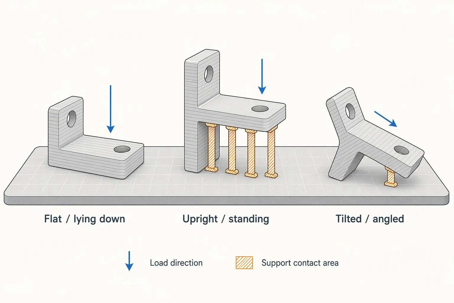
The practical consequence is simple: how a load lines up with the layer stack matters. A pull that runs along the layers is handled differently than the same pull trying to peel layers apart. How large that difference is depends on material, nozzle temperature, cooling, layer height, print speed, and nozzle geometry, so there is no fixed penalty to quote. The point is to know which direction your layers run before you decide what the part must survive.
What Orientation Changes: Six Trade-Offs
These factors move together. Turning one usually shifts the others, so you are choosing a balance, not maximizing every column.
Strength
Aligning the main load to run along the layers, in the XY plane, is a common starting point for functional parts. But load type matters: tension, bending, impact, and repeated fatigue loading all stress a part differently, and geometry and material change what "strong" means. Parts loaded from several directions rarely have one perfect orientation, so pick the orientation that protects the load path you care about most.
Surface Quality
Angled and curved faces printed as stacked layers show stair-stepping, and how visible it is depends on the surface angle relative to the bed, your layer height, and nozzle size. Top and bottom faces may show fewer visible layer steps, depending on the model and slicer settings, while vertical faces carry regular layer texture. Decide which faces are "show" faces before you rotate anything.
Overhangs
Overhangs are surfaces the printer must partly lay over air. How well a given overhang prints depends on material, cooling, layer height, speed, and the shape of the geometry. Overhang thresholds vary by slicer, material, cooling, layer height, and print speed. Use the sliced preview and a small test print to find what works for your setup — our guide on how to add 3D printing supports covers the mechanics.
Support Material
Rotating a model can move overhangs onto faces that matter less, or eliminate them entirely, which is the heart of how to reduce supports in 3D printing. Supports cost filament and time, and they leave marks where they touch the part.
Print Time
Orientation changes print time mainly through height, support volume, and travel. A tall orientation means more layers and more Z movement; more support means more material deposited and more time. Your slicer's time estimate is the practical way to compare candidates, but a shorter print isn't automatically the better choice.
Build-Plate Stability
A tall, narrow orientation has less first-layer contact and a higher center of gravity, which raises the risk of tipping or detaching mid-print. A brim or a wider footprint can help, and this matters most on tall prints and with warping-prone materials.
Hole and Feature Quality
A vertical hole axis may improve roundness in some models, but the result depends on geometry, material, and printer settings. Printed horizontally, the top of the hole is a bridge or overhang and tends to come out less round. Printed holes often land slightly undersized, and by how much varies with printer, slicer, hole size, and material, so test rather than assume a fixed clearance. Our FDM tolerances and clearances guide covers how to dial that in.
Orientation by Part Type: A Comparison Table
Use this table as a starting point to test, not a rule to follow. The right answer still depends on the load, the material, and the specific geometry in front of you.
|
Part type |
Sensible starting orientation |
Main trade-off to watch |
|---|---|---|
|
Brackets and functional parts |
Lay the main load-bearing face flat so layers run along the expected load; add material or ribs where loads cross layers |
Strength vs. support under angled features; check which faces are cosmetic |
|
Tall models |
Print upright with the widest stable base down; consider a brim |
Bed adhesion and tip-over risk vs. support and time savings from lying it down |
|
Flat plates |
Consider printing flat when a broad base and stable contact are priorities |
A large flat area can warp; layer lines show on the top face — check whether that face is visible |
|
Tubes and holes |
Consider a vertical hole axis when roundness is important, then verify it with a test print |
Taller print and more time vs. better hole roundness and no hole supports |
|
Enclosures |
Open side up, or on the least visible face; orient so the largest opening faces up |
Interior supports are hard to remove; outside faces may show support marks |
|
Models with text or logos |
Put the text on a top or bottom face (the XY plane) when possible |
Text on vertical faces reads through layer texture; small strokes may not resolve |
|
Large models printed in multiple pieces |
Orient each piece for its own strength and surface needs, then plan the joint |
Splitting changes load paths; joints need alignment features and may need extra strength |
For the text and logo row specifically, our guide to 3D printing text and logos covers stroke width and font choices that print cleanly.
Three Questions to Ask Before Rotating
Each answer narrows the realistic candidates.
Where Will the Main Load Go?
Identify the dominant load — a push, a pull, a bend, or a drop — and align it with the layers where you can. Multi-directional and impact loads complicate the picture, so protect the load path that matters most.
Which Surfaces Need to Look Best, and Where Can Supports Land?
Pick your show faces and orient them as top, bottom, or near-vertical surfaces, then route supports toward hidden or non-critical areas: undersides, interiors, and mating surfaces you plan to sand.
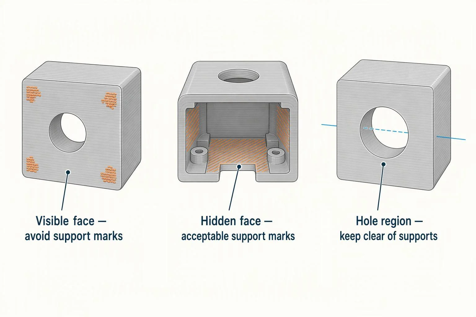
Does It Fit, and Does the Material Change the Risk?
Sometimes orientation decides whether a part fits at all, and a part that barely fits leaves no room for a brim. When nothing fits, splitting is the alternative — see our guide on how to split large 3D models. Materials also differ: some warp across large flat areas, others bond weakly between layers, and a few do both, so hedge against the failure mode your filament tends toward.
Comparing Candidates in Your Slicer
Keep a shortlist of two or three realistic candidates rather than testing every rotation. Duplicate the model, rotate each copy, slice them all, then compare print time, filament use, and support volume side by side. That comparison usually makes the trade-off obvious within a few minutes.
Slicer estimates are approximations, so check the preview too. Scrub through the layers and watch where supports land, which overhangs may sag, and any thin neck or long span that sits across the load path. If something looks questionable in the preview, it may indicate a problem on the final print. Our guide on how to read a slicer preview covers the full inspection workflow.
Test-Print Workflow Before the Final Model
A test print is cheaper than a failed final part, and it doesn't need to be the whole model. Print a scaled-down version, a sectioned slice, or just the critical region, using the same material and key settings as the final print — a test in a different filament tells you little about layer bonding or warping. Then load or flex it the way the real part will be used. Whichever candidate holds up and looks acceptable is your answer.
Common Orientation Problems and Fixes
Most orientation problems show up as a recognizable symptom, so match the symptom to the cause and adjust one thing at a time.
A clean break along a layer boundary usually means the load crossed layers or the interlayer bond was weak. Reorient so the main load runs along layers, then check nozzle temperature, cooling, and layer height as contributing factors. Support marks, meanwhile, appear wherever supports touch the part, so rotate until they land on hidden or sandable faces and remove supports the geometry doesn't need.
Rough surfaces usually come from stair-stepping on angled faces or support scars; reorienting show faces toward top, bottom, or vertical, plus a smaller layer height on those faces, often helps. Horizontal holes print as overhangs and tend to come out less round, so a vertical hole axis or drilling and reaming afterwards is the usual fix — our FDM tolerances and clearances guide covers the sizing.
Tall, narrow prints have less bed contact and a higher center of gravity. Try a brim, a wider base, slower first layers, or splitting the model into shorter pieces. And when print times balloon from height, support volume, and travel, compare slicer estimates across orientations to see whether a different rotation cuts support without hurting strength.
FAQ
Is there one best orientation for 3D printing?
No. Strength, surface finish, supports, time, and stability trade off against each other, and each model weights them differently depending on material, geometry, and load.
Why did my part break along a layer line?
The break followed the weakest bond — between layers. Align the main load with the layer plane where you can, and check temperature, cooling, and layer height, since all three affect how well layers fuse.
How should I orient a model so text or a logo prints cleanly?
Text on a top or bottom face tends to print most legibly, while vertical text reads through layer texture. For stroke width and font guidance, see our guide to 3D printing text and logos.
Is the fastest orientation always the best one?
No. A fast orientation that puts the load across layers or ruins a visible face can cost more in reprints than it saves in print time.
Pre-Slicing Orientation Checklist
Run through this before you hit slice:
- Identify the main load direction and align it with layers where possible
- Mark your show faces and orient them to top, bottom, or vertical
- Route supports to hidden or non-critical faces
- Confirm the part fits with room for a brim
- Compare two or three candidate orientations in the slicer
- Inspect supports, overhangs, and first-layer contact in the preview
- Print a small test piece before committing
Orientation is a call you make for each model, not a default you accept. Start with your load path and show faces, compare a couple of candidates, and let a test print settle the rest.