

Quick Answer: Which Method Fits Your Part?
Most real projects mix these methods rather than picking one. A common pattern: calipers for hole spacing and thickness, a scan for a complex curved surface, and CAD for the final part.
|
Method |
Best for |
Strengths |
Limitations |
Typical output |
|---|---|---|---|---|
|
Manual measurement |
Brackets, plates, simple prismatic parts |
Fast, cheap, no equipment beyond calipers |
Misses freeform curves; slow on organic shapes |
Hand-drawn dimensions or direct CAD |
|
3D scanning |
Complex curves, sculpted or asymmetric shapes |
Captures overall form quickly |
Needs cleanup; struggles with shiny, dark, clear, or hidden surfaces |
Point cloud or mesh |
|
CAD reconstruction |
Parts that must fit, be edited, or be redesigned |
Editable features, clean holes, real design intent |
Most effort; requires interpreting the original design |
Parametric solid (STEP) |
|
Direct mesh editing |
Organic or cosmetic shapes with minor changes |
No reconstruction needed; preserves surface detail |
Hard to change dimensions precisely; mesh defects carry through |
Edited mesh (STL/3MF) |
Start with the tightest functional requirement — usually a hole, a mating face, or an overall envelope — and choose the method that measures it most reliably.
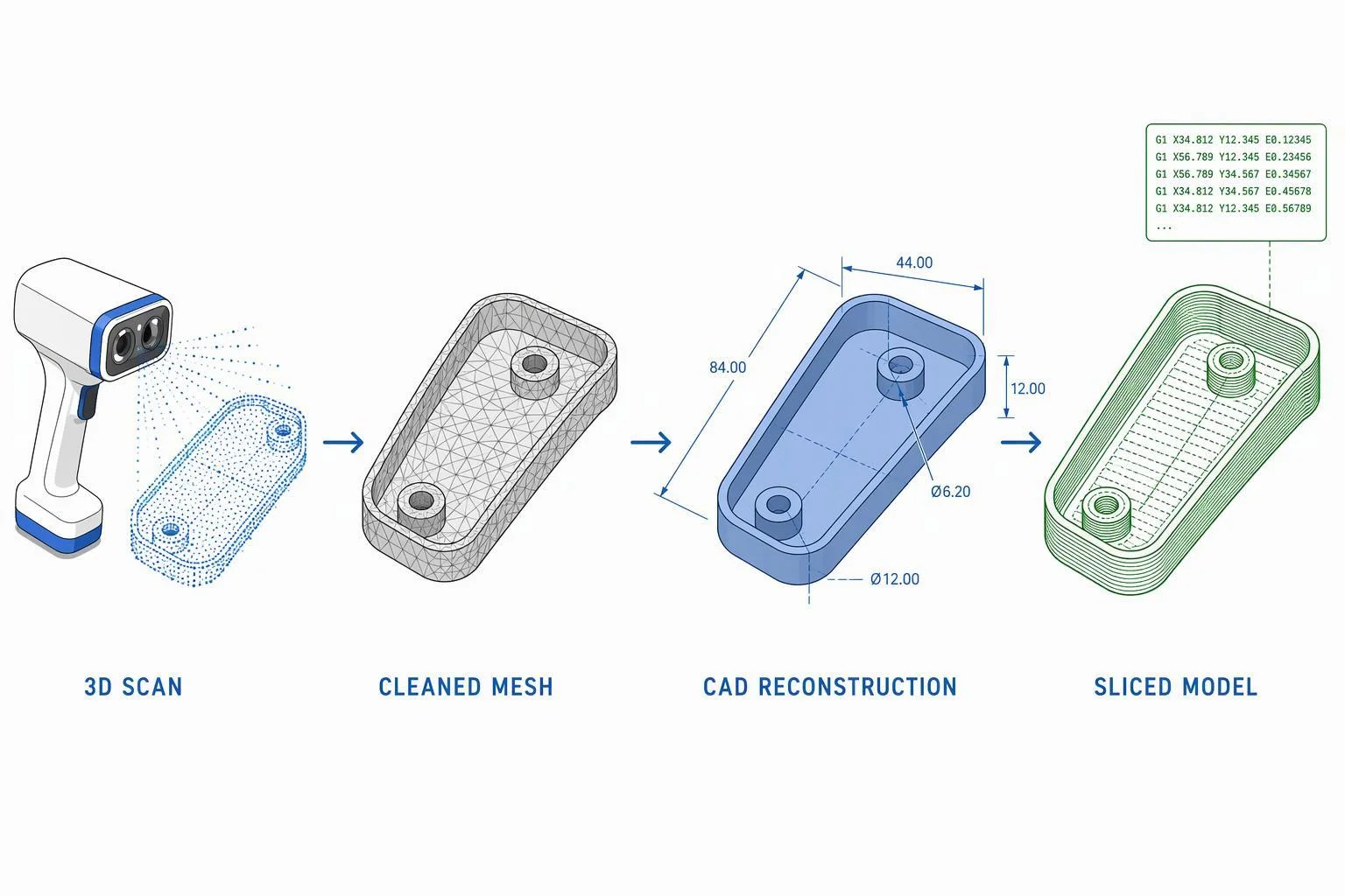
The Complete Workflow: From Physical Object to Printed Part
The ten stages below run in order because each one reduces the chance of wasting filament on a part that can't work. Expect to loop back: a failed test fit usually sends you to Step 4 or Step 6, not to the printer.
1. Choose a Suitable Object
Scan-friendly parts are matte, rigid, and visible from most angles. Transparent, mirror-finished, flexible, or heavily undercut parts fight the scanner, and small simple parts are often faster to measure by hand.
2. Capture the Object with a 3D Scanner or Other Scanning Method
Handheld structured-light or laser scanners, photogrammetry from overlapping photos, and turntable setups all produce usable data. Keep lighting stable, overlap your views, move at a steady pace, and hold a consistent distance; add extra passes around hidden areas.
3. Clean and Align the Scan
Remove background and stray points, register multiple scans into one coordinate frame, and patch only obvious gaps. Smooth where noise is clearly not real geometry — over-smoothing erases the small features the part depends on.
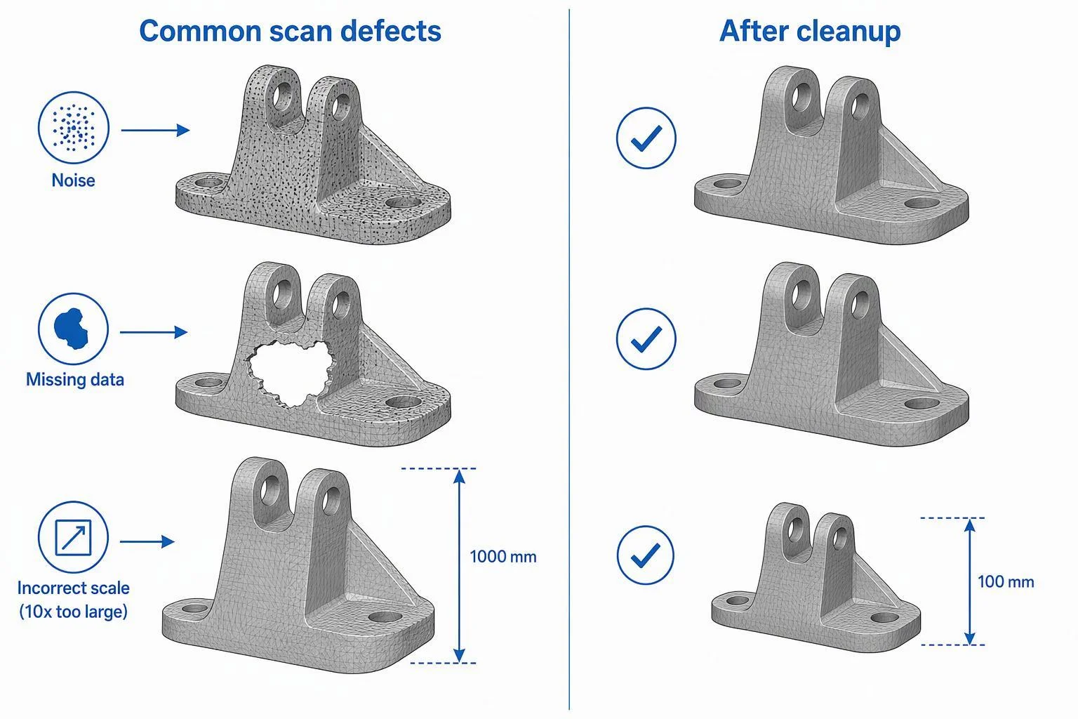
4. Check Scale and Reference Dimensions
STL carries no unit information, so scale errors often show up as clean factors like 10, 25.4, or 1,000. Measure a known distance on the real object and the same distance in the scan, apply one uniform factor (real ÷ scanned), then verify a second dimension. Never stretch a single axis to force one number to match — that hides distortion.
5. Identify Important Surfaces, Holes, Edges, and Interfaces
Separate functional geometry from cosmetic geometry. Datum surfaces, mating faces, hole centers and diameters, edge profiles, snap features, and screw bosses decide whether the part works; the overall outer shape usually does not.
6. Rebuild or Edit the Model in CAD
Reconstruct clean parametric geometry when the part must fit, be edited, or be redesigned; edit the mesh directly when the shape is organic and only minor changes are needed. Worn or broken regions are rebuilt from functional evidence, not copied from the scan.
7. Export as STL or Another Suitable Format
STL is pure mesh and unitless. 3MF can store unit and project-related data, but the information preserved depends on the software that creates and imports the file. STEP usually stores editable solid geometry, but it does not necessarily preserve the original CAD feature history or design tree. Export the format that matches the next step in your pipeline — our guide to STL, 3MF, and STEP compared covers what each one stores and where each one breaks down.
8. Repair the Mesh if Necessary
A watertight, manifold mesh is a closed skin with a clear inside and outside, where every edge has exactly two faces. Close holes, remove duplicate faces, recalculate flipped normals, and delete non-manifold fins — but be careful with large automatic patches, which can invent geometry that was never there.
9. Review the Slicer Preview
Inspect layer by layer: wall thickness on thin features, hole sizes, support placement and interface gaps, overhangs, and whether small details survive slicing. Our guide on how to read a slicer preview has a full checklist of warning signs.
10. Print a Small Test Piece First
Print just the mating region, a hole-and-shaft coupon, or a scaled section, oriented the way the final part will print. That validates fit-critical features in minutes instead of hours, and tells you what to measure by hand before committing to the full part.
Common 3D Scanning Challenges and How to Handle Them
Most scan problems trace back to physics, line of sight, or units. Diagnose the cause before reaching for smoothing tools.
Shiny, Dark, Transparent, and Reflective Surfaces
Many structured-light and laser scanners use projected light and triangulation, while photogrammetry relies on visual features in overlapping photographs. Both approaches can struggle when the surface has poor visual contrast or limited visibility. Mirror finishes throw light away, clear parts pass it through, and deep blacks absorb it — producing holes, noise, or ghosted surfaces. A thin removable matting spray, retroreflective targets for tracking, adjusted exposure, and a different viewing angle all help; some surfaces simply need preparation before capture.
Missing Areas and Holes in the Scan
Scanners rely on line of sight and cannot see through or behind objects. Capture from more angles, merge the passes, and then decide: patch a small gap on a continuous surface, or reconstruct a hidden interface from measurements rather than guessing.
Noise and Uneven Mesh Surfaces
Distinguish random surface noise from real texture and from tracking drift, which shows up as warping across a large part. Smooth selectively, rescan with steadier lighting and slower movement, and use targets to limit accumulated alignment error.
Incorrect Scale or Missing Units
Fix it in four steps: measure a known distance on the real object; measure the same distance in the scan; divide real by scanned; apply that one factor uniformly and verify a second dimension. All axes off by the same factor is mis-scaling; one axis off is distortion, and stretching won't fix it.
Thin Walls and Small Details
Features smaller than the scanner's effective resolution blur together, and thin walls may scan as a single surface or vanish. Measure thin features by hand and model them explicitly instead of trusting the scan.
Hidden Surfaces and Undercuts
Internal channels, back faces, and undercuts are invisible to line-of-sight capture. Disassemble the part, scan it in sections, cut a cross-section, or reconstruct the hidden geometry from what it has to fit.
Scan-to-Mesh vs. Scan-to-CAD vs. Direct Mesh Editing vs. Measurement-Based Reverse Engineering
Reverse engineering for 3D printing is the overall goal, and four routes get you there. Scan-to-mesh keeps the scan as a cleaned, repaired surface: low editability, low to moderate effort, best for cosmetic parts and as-built copies. Scan-to-CAD rebuilds a parametric solid from the scan data, which costs the most effort but gives you editable features and history for parts that must fit or be redesigned. Direct mesh editing sits in between, roughly moderate effort, suited to sculpting small changes into an organic shape. Measurement-based reverse engineering skips the scanner entirely and builds CAD from calipers and gauges — low to moderate effort, and usually the fastest route for prismatic brackets and plates.
A scan-to-mesh result is not automatically a CAD model: a triangulated surface doesn't contain nominal hole sizes, concentric relationships, or editable features, so those relationships usually have to be rebuilt when the part must fit or be revised.
Practical Examples: Which Workflow Fits Which Job?
Four short cases show how the decision logic plays out. None of them uses a single method exclusively.
Recreating a Broken Plastic Cover
Scan the intact half for reference, mirror it if the part is symmetric, then rebuild the broken region and measure the mounting features by hand. This is a scan-to-CAD job.
Designing a Replacement Bracket
Start with calipers: hole spacing, thickness, and load direction. Use a scan only for the curved mounting surface. Brackets usually need design changes, which favors parametric CAD over mesh editing.
Copying a Custom Adapter
Measure the mating interfaces precisely, scan the outer form, and add clearance deliberately rather than copying the original's fit. Our FDM tolerances and clearances guide gives starting values, but treat them as starting points and verify them on your own machine.
Reproducing a Discontinued Household Part
Cosmetic household parts often tolerate a direct mesh workflow with only critical interfaces rebuilt. Correct worn features instead of copying them; a distorted original should not become the new nominal.
Troubleshooting Table: When the Printed Part Doesn't Work
Work from the cheapest check upward. A scale or unit error costs nothing to fix; reprinting a warped part costs hours. The fixes below follow that order.
|
Symptom |
Likely cause |
Practical fix |
|---|---|---|
|
Scanned model is too large or too small |
STL is unitless; import assumed the wrong unit |
Check for a clean factor such as 10, 25.4, or 1,000; apply one uniform scale factor and re-verify a second dimension |
|
Replacement part does not fit |
Clearance too tight or too loose; wrong measurement |
Re-measure the original; adjust modeled clearance; confirm units on both export and import |
|
Holes are blocked or distorted |
Hole printed undersized; support residue; overhang sag in horizontal holes |
If your slicer provides XY-hole compensation, use it cautiously after measuring a test print; otherwise adjust the CAD geometry and validate with another test; clean or sand the bore; reorient the hole axis or add a lead-in chamfer |
|
Mesh has gaps or non-manifold geometry |
Missing scan data; duplicate faces; flipped normals |
Close small holes, remove duplicate faces, recalculate normals; rebuild large gaps from measurements rather than auto-filling |
|
Printed part is warped or misaligned |
Poor bed adhesion; uneven cooling; warped mating faces; support marks |
Clean the bed, control cooling, flatten contact faces, and add alignment pins or keys with realistic clearance |
|
Scan contains too much surface noise |
Difficult surface; unstable tracking; drift across a large part |
Rescan with better lighting, targets, and slower movement; smooth selectively rather than globally |
How to Validate the Final Design Before the Full Print
Validation is a loop, not a final checkbox. Fit-related dimensions should be confirmed with a test print rather than trusted from CAD alone, because your printer adds its own bias to every dimension.
Compare Key Dimensions
Check interfaces, hole spacing, and overall envelope, measuring the printed test and the original with the same tool and the same method.
Check Mating Surfaces
Look at contact area, flatness, and clearance where surfaces actually touch, allowing for support residue and first-layer flare.
Use Test Sections or Partial Prints
Isolate the fit-critical region into a small coupon, orient it the way the final part will print, and test it by hand before committing filament.
Test the Real Assembly
Install the part in its actual context: under load, at temperature, through its full range of motion. Watch for binding, cracking, and loosening.
Revise the CAD Model Based on the Test Result
Translate the result into a specific change: clearance, feature size, or orientation-dependent compensation. Avoid a global scale tweak, and don't stack slicer compensation on top of CAD compensation.
FAQ
Short answers to the questions readers ask most often about going from 3D scan to 3D print.
Can I 3D print directly from a scan?
Sometimes, if the mesh is watertight, correctly scaled, and the part doesn't need precise fits. Expect cleanup and mesh repair first, and expect limited editability afterward.
Is a 3D scanner required?
No. Manual measurement, photogrammetry, and sectional tracing can all feed a printable model. Scanning helps most when the geometry is complex and curved.
What is the difference between STL and CAD after scanning?
STL is a triangulated surface mesh with no feature history and no unit information; CAD is editable parametric geometry. Converting between them is not lossless in either direction.
How do I fix an incorrect scan scale?
Measure a known distance on the real object and the same distance on the scan, apply one uniform factor (real divided by scanned), verify a second dimension, then confirm units on export and import.
How accurate does a scan need to be for FDM printing?
There is no universal number. It depends on your printer, material, and the fit the part requires. Match scan quality to your tightest functional feature and validate with a test print.
Conclusion: Scan, Rebuild, Test, Repeat
Treat the scan as reference data, not a finished model. Verify scale before anything else, rebuild functional features in CAD, and let a small test print rather than the slicer preview alone decide whether the design is ready. If you want to go further with functional part design, our guide to 3D printed jigs and fixtures covers datum surfaces, locating features, and validation in more depth.
Key Takeaways
- A 3D scan produces a mesh, not an editable CAD model; reconstruction is often part of the job.
- Verify scale and units before you model anything, and never scale a single axis to force a fit.
- Functional features, not overall shape, decide which workflow you need.
- Mesh repair and a layer-by-layer slicer review catch many problems before the printer does.
- Test prints validate fit; CAD alone cannot.
- Accuracy depends on the scanner, object, surface, calibration, software, and workflow, so no single tolerance applies to every job.