




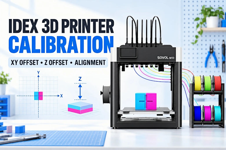
An IDEX machine carries two independently driven toolheads that share the Y and Z axes, so each head needs its own positional truth. There is no universal XY offset, Z offset, or flow value. Any number you see, including one from another owner of the same model, is a starting reference that your own test print has to confirm. Every step below is a check you run on your own machine, and toolhead alignment is confirmed the same way: by the print in your hand.
Key Takeaways
- Four settings get blamed for one symptom: XY offset, Z offset, extrusion flow, and toolhead alignment.
- Follow a consistent starting order, then repeat it after any nozzle, toolhead, or belt change.
- No universal values exist for XY offset, Z offset, or flow; published numbers are starting references only.
- Your own two-color test print is the most practical way to verify the result.
Understand what each calibration stage controls
IDEX 3D printer calibration is four separate corrections that beginners routinely treat as one. XY offset decides where the second nozzle lands in the horizontal plane. Z offset changes where the nozzle starts relative to the bed, and it is a user-defined value: negative brings the nozzle closer to the build surface, positive moves it further away (Wevolver's Z-offset explainer, 2022). Extrusion, or flow, decides how much material each extruder actually pushes. Toolhead positioning decides whether each head repeats its docked position after a tool change.
|
Stage |
What it controls |
Axis or quantity |
Symptom when wrong |
Set in |
|---|---|---|---|---|
|
XY offset |
Where the second nozzle lands horizontally |
X and Y, in mm |
Colors offset or outlines doubled on one side |
Firmware or slicer |
|
Z offset |
Nozzle height above the build surface |
Z, in mm |
First layer squashed, gappy, or not sticking |
Firmware or slicer |
|
Extrusion / flow |
Volume of filament each extruder pushes |
Flow rate, in percent |
Thin walls, gaps inside a single color |
Slicer |
|
Toolhead positioning |
Repeatability of the docked position |
Mechanical position after each tool change |
Alignment drifts as a print runs |
Firmware and hardware |
The distinction matters because the defects overlap visually. If one toolhead under-extrudes, no amount of XY offset adjustment will fix the print: the gap you are chasing is a flow problem wearing an alignment costume.
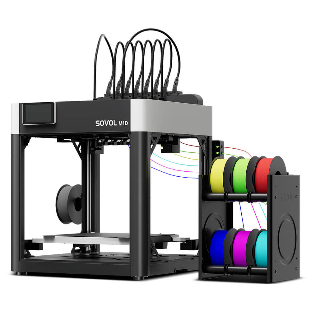
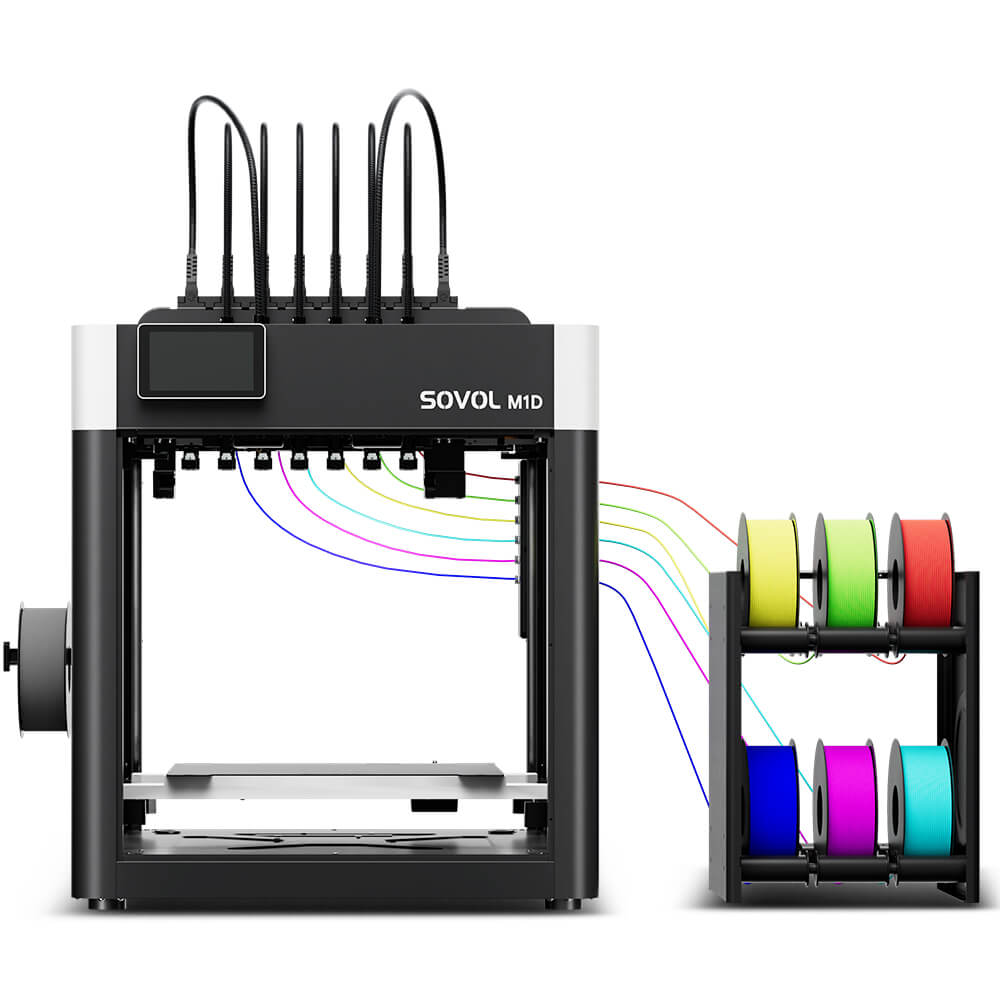
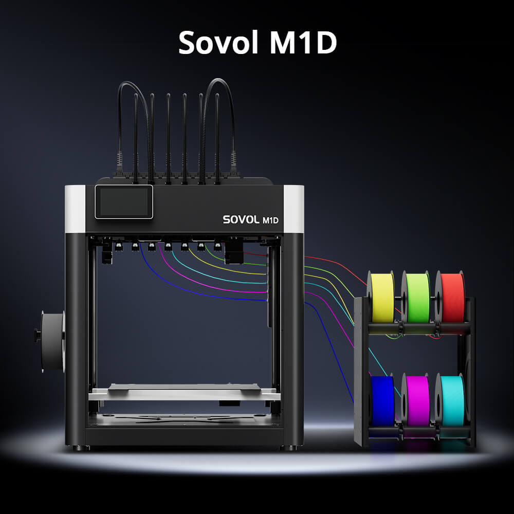
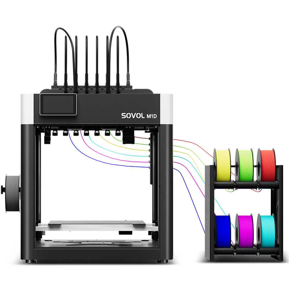
Machines differ in how much of this they automate. Sovol's documented M1D calibration system uses a rear camera for XY offsets and two toolhead-mounted cameras for per-nozzle extrusion accuracy, with a mechanical Z-lift compensating left-toolhead height. Those are vendor descriptions of what the system does, not independent test results, and they do not remove the need to verify the result yourself.
Recognize the signs of poor IDEX 3D printer calibration
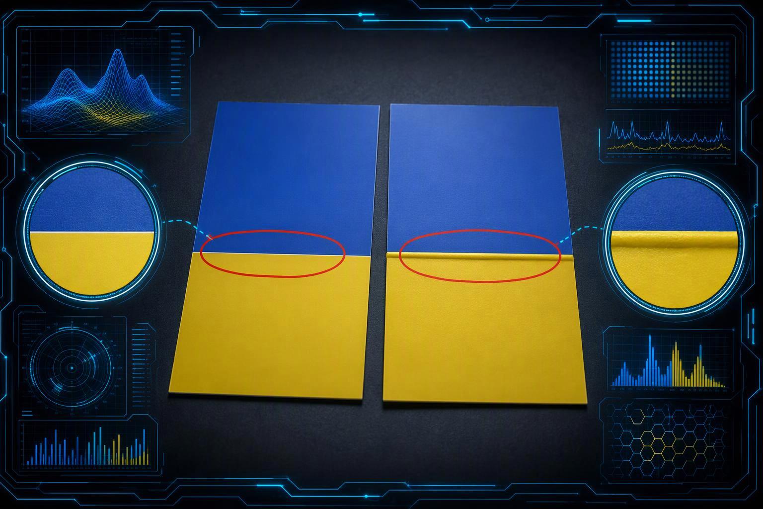
Most IDEX calibration problems announce themselves in the print, not on the screen. Print the two-color test model, then look at the boundary where the colors meet: a visible gap means the offset is off in one direction, an overlap ridge means it is off in the other, and either one is a starting point for a small adjustment, not a verdict on the machine.
The defect tells you which axis to touch. A left/right shift of one copy points at X, a front/back shift points at Y, and skirts or brims that no longer sit where the model was placed are the same error seen from the bed, which is what Copy mode needs from your calibration to hold steady.
Height errors look different again. When one nozzle sits lower than the other, a lower nozzle can scrape the bed or part, over-squishing one copy while the other under-extrudes. Uneven first layers between the two regions, or a doubled outline on one color, usually trace back to that height mismatch rather than to XY.
Some drift has physical causes worth knowing before you chase numbers: loose or non-square mounting, thermal expansion between cold and hot states, and docking repeatability, which is why offsets drift when the machine heats up or after a tool swap.
Key Takeaway: A visible gap and an overlap ridge are opposite-direction errors. Both are starting points for a small adjustment, not a verdict on the machine.
Know when to check or repeat calibration
Treat IDEX 3D printer calibration as a maintenance step, not a one-time fix. Repeat it after any toolhead install or replacement, a nozzle change, moving or transporting the printer, routine maintenance, or a firmware or slicer profile change. Any multi-color print that shows misalignment is also a trigger.
Offsets shift between a cold and a hot machine. Temperature changes can affect mechanical alignment and nozzle positioning, so calibration results may differ between a cold and a warmed-up printer. Loose or non-square mounting changes effective X/Y position the same way. Calibrate cold and your values are a starting reference, not a final one.
Run the step-by-step IDEX 3D printer calibration workflow
Learning how to calibrate an IDEX 3D printer gets easier once you accept that the order matters as much as the values. A first layer that is not stable makes every later measurement meaningless: if one nozzle sits high, the XY offset you measure against it is measuring the wrong thing. The sequence below follows the recommended order of operations on an IDEX machine: settle the first layer and bed level, match both nozzles' effective Z height, then measure nozzle-to-nozzle X and Y offsets. Z height has to be stable first, because an XY result measured against an unstable first layer is not trustworthy. Work through it in that order and IDEX 3D printer calibration stops being a guessing game.
Step 1: Inspect the toolheads and docking areas
By the end of this step you know whether the hardware can hold a calibration at all. Check for loose or non-square mounting, play in the carriage, and debris or filament scraps sitting in the dock. Then confirm each toolhead seats fully and repeats its position. Dock and undock each toolhead several times, by hand or through the firmware, and watch whether it returns to the same point. It has to, because docking or homing repeatability is what keeps the nozzle-to-nozzle offset from drifting between tool changes. While you are in there, tighten the nozzle hot, then let it cool, the sequence Rat Rig documents for its own machines.
Step 2: Confirm nozzle and toolhead assignments, then verify extrusion
Both extruders have to push material consistently before you touch a single offset. Confirm which toolhead is T0 and which is T1 in the firmware and in the slicer, then check that both nozzles are clean and both extruders feed without slipping or grinding. This comes before XY offset for a practical reason: an under-extruding toolhead leaves a gap in the print that looks exactly like misalignment, and you will spend an hour chasing dual extruder alignment that was never the problem. Extrude a short length from each toolhead and compare the two strands. An obviously thinner or inconsistent one means fix flow first. No flow multiplier or wall-thickness figure is given here, because a university calibration write-up on measuring extrusion treats these values as state-dependent: any number you find elsewhere is a starting reference that depends on your printer and your filament.
Step 3: Run the automatic calibration your machine supports, then verify it
Run whatever routine your machine provides, then treat it as a measurement rather than a result. Firmware-level automation exposes real controls: Klipper switches carriages with SET_DUAL_CARRIAGE, and it applies the second tool's relative offset when activating T1 through applying the second tool's relative offset when activating T1. What automation cannot do is confirm its own output. Vision Miner's calibration wiki notes that dirty nozzles or bent heat breaks produce incorrect offsets, and instructs owners to run a test print after auto calibration, toolhead service, or whenever color shifts and gaps appear.
⚠️ Warning: Automation measures the offset. It does not confirm the result.
Your checkpoint is the test model in Step 6, inspected from all sides.
Step 4: Check Z offset and first-layer contact
Z offset calibration 3D printer work comes down to one rule: adjust the first layer live, not by a fixed number. Prusa's own procedure has the user turn a knob while the printer lays down a zig-zag pattern, and states plainly that you must check visually when adjusting the height, not by a set value; measuring the printed layer with calipers is not a recommended method either. Check the manufacturer's procedure for setting the effective Z height of each toolhead. Some IDEX printers provide separate adjustments, while others use mechanical compensation or a shared reference toolhead. A nozzle printing higher or lower than the other is a common cause of a two-color print that fails at the base, so settle this before you touch any XY value. Your checkpoint is a first layer that is smooth, slightly squished, and consistent across the whole bed.
Step 5: Check XY offset and toolhead alignment
IDEX XY offset calibration only means something once both nozzles sit at the same effective Z height, which is why it comes after the Z stage. The direction logic is simple: a wrong X offset shows as a left or right shift at the color boundary, a wrong Y offset as a front or back shift. Print a small two-color alignment test and look at the boundary line. A visible gap means the offset is pulling one way, an overlap ridge means the other. No universal XY offset value exists, so adjust, reprint, and compare rather than copying a number from a forum.
Step 6: Print a two-color test model and inspect it
Print a small two-color model that crosses the boundary several times, then look at it from every side. Even color distribution and a clean seam mean the calibration held. A shifted outline, a double image, or a gap line tells you which offset to revisit. Vision Miner's documented cylinder test is printed 5 to 10 layers and inspected from all sides for equal color distribution, which is a faster check than a full multi-hour print.
Troubleshoot common IDEX calibration problems
Start with the symptom, then run the check that matches it. Most IDEX faults trace back to one of six causes, and the table below maps each symptom to the step that resolves it.
|
Symptom |
Likely cause |
Recommended check |
|---|---|---|
|
Colors land off-register on a two-color print |
dual extruder alignment drift between toolheads |
Step 5: check XY offset and toolhead alignment |
|
One toolhead prints higher or lower than the other |
Different toolhead heights between the two nozzles |
Step 4: check Z offset and first-layer contact |
|
First layer looks different in each region |
Uneven bed contact across the two tool positions |
Step 4: check Z offset and first-layer contact |
|
Tool changes miss or repeat inconsistently |
Docking or homing repeatability |
Step 1: inspect the toolheads and docking areas |
|
One tool under- or over-extrudes |
Uneven extrusion between the two tools |
Step 2: verify extrusion on both nozzles |
|
Copy or Mirror prints do not line up |
Offset values that Copy mode depends on |
Step 5: check XY offset and toolhead alignment |
One caution before you chase an alignment fix: a gap or seam you are trying to close may be a flow problem rather than an alignment problem. Verify extrusion on both tools in Step 2 before you adjust offsets.
Why calibration values and test results vary
No universal IDEX offset number exists, because an offset compensates for a chain of interacting variables rather than a fixed mechanical error. Printer mechanics, filament viscosity and diameter tolerance, layer height, temperature, build surface condition, and slicer profile all feed into the same value, as peer-reviewed work on how layer height changes extrusion describes: layer height sets volumetric flow demand, so changing it changes the pressure the extruder must build. Temperature moves in the same direction, which is why offsets drift when the machine heats up. A number that worked on someone else's machine encodes their hardware and their filament, not yours.
Pro Tip: Change one variable at a time and reprint the test model. Two changes at once make the result unreadable, because you cannot tell which adjustment produced the difference you see.
What the Sovol M1D documents for calibration

Sovol is an open-source 3D printer manufacturer, and the calibration features described in this section are the ones documented for the M1D. They are product information, not independent test results.
For IDEX 3D printer calibration, the M1D documents three mechanisms. A rear camera handles XY offset calibration across the toolhead system, while two toolhead-mounted cameras separately calibrate each nozzle's extrusion accuracy; Sovol states this completes calibration up to 2.5x faster than conventional methods. A built-in mechanical Z-lift adjusts the left toolhead's height and compensates Z-offset differences in real time. Bed measurement uses eddy-current scanning for non-contact bed measurement, which avoids physical probing of the plate.
The boundary matters for toolhead alignment. Documented features describe what the system does, not that it removes manual checks, and no claim is made that alignment holds over hundreds of hours. The verification steps in this guide are still yours to run.
Frequently asked questions
How long does IDEX calibration take?
Plan for 30 to 60 minutes for a full pass: inspecting both toolheads, confirming extrusion, running the machine's automatic routine, then printing and reading a two-color test model. The test print dominates the time. It gets shorter on repeat runs because you only redo the stages a hardware or material change actually affected.
Does automatic calibration remove the need for manual checks?
No. An automatic routine sets the offsets the machine can measure; it cannot tell you whether the result is right. You still run a test print after auto calibration and inspect the color boundary, because a correct-looking routine can still leave a visible shift in the finished part.
What if the two toolheads print at different heights?
That is a Z-offset difference between nozzles, not an XY problem. Recheck that both nozzles are clean and seated, then re-run the Z stage so the second toolhead is set relative to the first. Confirm on a first layer printed with each nozzle in turn.
Does the same offset work for every filament and layer height?
No. Offsets are state-dependent: nozzle wear, toolhead seating, filament diameter, and layer height all shift the correct value. Peer-reviewed work on how layer height changes extrusion shows the deposited bead changes with layer height, so a value tuned at 0.2 mm is a starting reference, not a constant.
Is IDEX inherently more accurate than a single-extruder printer?
No such claim holds. What makes an IDEX printer an IDEX printer is independent toolheads plus duplication and mirror modes, which is a capability difference, not an accuracy one. Print accuracy still comes from your Z offset calibration 3D printer settings and mechanical condition.
Conclusion
IDEX 3D printer calibration comes down to a short, repeatable loop: confirm the mechanics, verify extrusion on both tools, run the automatic routine your machine supports, then check the result against a test print. Run it once and you have a baseline; run it again after any nozzle swap, toolhead change, or firmware update and you have a procedure that keeps two colors landing where the slicer says they should.
Before a complex multi-color print, work through this checklist:
- Mechanics sound: toolheads dock cleanly, no play in the mount
- Extrusion consistent on both tools
- Automatic calibration run and verified, not just started
- XY offset checked against a test print
- Both first layers matching in feel and appearance
- Test model inspected before committing a long print
If you would rather see how one machine automates part of this workflow, the Sovol M1D documents camera-based XY calibration and a mechanical Z-lift that compensates for height differences between nozzles. Those are vendor-documented features, not independent test results, so treat them as a starting point and verify with your own test print.