




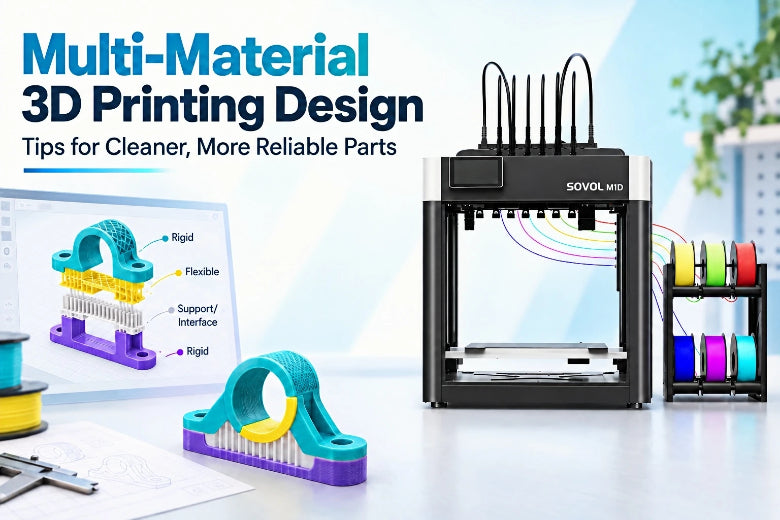
That's the premise of this guide: a design-first workflow for multi-material 3D printing, from splitting a part into functional regions to running a small test print before you commit filament to the full job. Along the way you'll meet the terms that matter. A purge block is the waste tower the printer builds while clearing one material from the nozzle before the next one starts. A tool change is the swap itself, and on a tool-changer or an IDEX (independent dual extruder) machine, it happens mechanically rather than by purging. An interface is the boundary layer where two materials meet, and it's where most of these prints succeed or fail.

Key Takeaways
- Failures at the material boundary are usually decided in CAD, not in the slicer.
- Two materials that don't bond chemically need geometry, not hope, to hold them together.
- Validate the design with a small coupon before committing to the full part.
Multi-Material 3D Printing Design Starts With Regions, Not Settings
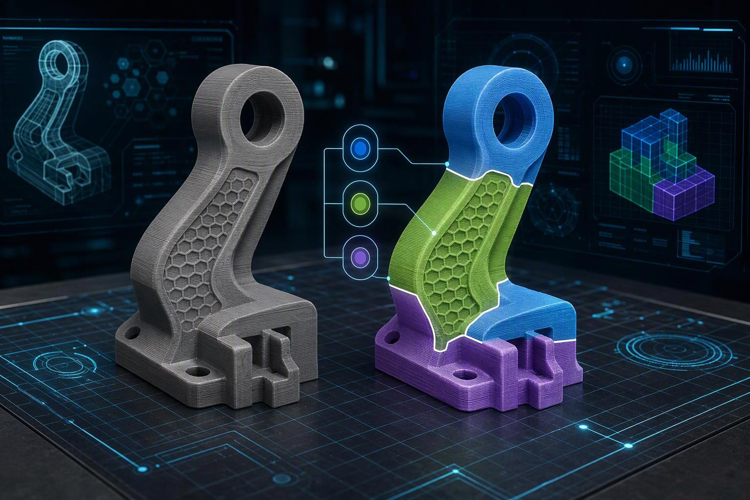
Multi-material 3D printing design is a CAD decision, not a slicer setting. Before you touch a temperature tower or a purge multiplier, decide which regions of the part need which material. A region is a volume of the model assigned a material for a functional reason: a rigid core, a flexible grip, a soluble interface under an overhang. A color swap is cosmetic, applied to the same geometry for appearance only. The two are not interchangeable, and treating a functional boundary as a color swap is one of the most common ways a multi-material 3D printing workflow goes wrong.
The failure tends to show up at the boundary, not in the print. Prusa's multi-material guide explains why: because each polymer has a different composition, "sometimes the chemistry just isn't a match, and the layers don't adhere as they should." Purging more aggressively won't fix a joint between two materials that were never given a designed interface.
Key Takeaway: The boundary is where multi-material parts fail, so plan regions before you open the slicer.
Prerequisites: What You Need Before You Design
Before you split a single body into regions, confirm your setup can actually deliver two materials in one print. The checklist is short, but skipping it is how multi-material 3D printing design turns into wasted filament.
- A CAD tool that supports multi-body parts or region assignment. You need to divide one model into separate solids or assign faces to different bodies, then export STL or 3MF. Fusion 360, SolidWorks, and FreeCAD all handle this.
- A slicer that manages multi-material tool assignment. OrcaSlicer, the M1D's listed default slicer, is a common choice; PrusaSlicer and Bambu Studio work the same way.
- Filament that is dry and stored sealed. Water-soluble supports are unforgiving here. Prusa's knowledge base on water-soluble materials notes that PVA+ and BVOH exposed to humidity "deteriorate in a matter of a few months and go soft at a much lower temperature," so reseal spools with silica immediately and use a drybox.
- A small calibration or test part. Start with a small test coupon that represents your actual interface. It verifies adhesion and tool changes before you commit a full print.
- A printer that can change material. Either a single-nozzle purge-based system or a tool-changing machine.
Assumed knowledge: you should be comfortable splitting a body and exporting an STL or 3MF. Time: roughly 30 minutes to prepare. Difficulty: intermediate.
Step 1: Split the Part by Function, Not by Color
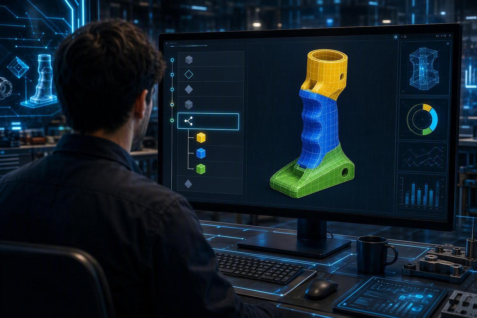
By the end of this step, you'll have a multi-body model where every body maps to one material job. That's the core of how to design multi-material 3D prints: a region earns its own material because it does something, not because two colors look good together.
Ask of each region: what job does it do? A grip surface, a wear pad, an overhang that needs dissolvable support, a living hinge that has to flex. If you can't name the job, it doesn't need its own material.
In CAD, split by plane or by sketch, then keep a small overlap or interlock allowance at the joint instead of a zero-clearance butt joint. A zero-gap butt joint between two materials is one common reason for weak material boundaries, because nothing mechanically locks the two regions together.
Pro Tip: Name each body for its material job, not its color. core, grip, support_interface makes slicer assignment unambiguous later.
Verify your result: list every body and say in one sentence what material it needs and why.
Step 2: Design the Interface Between Two Materials
Two materials that do not bond chemically need geometry to hold them together, and that geometry is the designer's job, not the slicer's. The Multi-Material Interlocking feature in PrusaSlicer exists precisely because two polymers often "do not adhere as they should"; it generates a cross-hatched boundary between the filaments so the bond is mechanical rather than chemical. You can build the same idea into the model: add dovetails, through-holes, ribs, or a stepped, cross-hatched boundary, give the interface real surface area instead of a flat plane, and orient it so load runs across the joint rather than peeling it apart.
⚠️ Warning: A flat, zero-clearance butt joint between two materials is one common setup for a weak part. It looks fine on the bench and separates under load.
A weak bond is sometimes the point. Prusa's multi-material guide recommends pairing materials that adhere poorly, explicitly PLA with PETG, when you want easy-peel supports. The same logic applies to soluble interfaces: Prusa's knowledge base notes that PVA+ and BVOH adhere well when printed directly onto PLA and PETG but poorly to smooth PEI and textured steel sheets, which matters when you are choosing between a soluble interface and full soluble support.
Verify your result: you can state whether your interface is meant to hold or to release, and your geometry matches that intent.
Step 3: Choose Material Combinations That Match the Job
There is no universal list of filaments that bond to each other. Adhesion depends on the specific formulations, the nozzle temperature each one wants, the geometry of the interface, and your slicer profile, which is why the practical approach is to pick by function first and verify with a test print second.
Most second materials do one of three jobs:
|
Job |
What the second material does |
Example pairing |
|---|---|---|
|
Support interface |
Sits only in the dense layers between support and model |
PLA or PETG model with PVA or BVOH interface |
|
Rigid plus flexible |
Adds grip, damping, or a soft contact surface |
PETG core with TPU skin |
|
Wear or color surface |
Provides a hard-wearing or visibly different outer face |
Any base material with a contrasting top layer |
The support-interface job is the most efficient use of a second material. In the SOLUBLE INTERFACE preset, soluble filament is applied only in the denser layers between the support structure and the model, so the bulk of the support still prints in ordinary filament. You get clean undersides without spending soluble material on scaffolding nobody sees.
For rigid-plus-flexible parts, temperature spread is the constraint that catches people out. In Prusa's worked PETG + TPU hinge example, PETG prints at a 250 °C nozzle and TPU at 225 °C. That 25 °C gap is manageable, but each material also wants its own flow rate and part cooling, so a pair with nozzles far apart is harder to print cleanly than a close pair. These figures come from specific example profiles and should not be treated as universal settings.
Verify your result: before you slice, write down the nozzle temperature for every material in your part and confirm your printer can hold each one. If you cannot name both temperatures, you are not ready to print.
Step 4: Plan the Model for Your Printer's Material-Change Method
A single-nozzle purge-based system and a tool-changing system impose different design rules, so plan the model for the machine on your bench. On a purge-based multi-material unit, every change costs filament: Prusa's knowledge base lists a default filament-change purge of 140 mm³ on the MMU3 and MMU2S, and the recommended purge volume for water-soluble supports rises to at least 200–240 mm³. Both are single-nozzle MMU figures and do not describe tool-changing systems. These figures come from specific example profiles and should not be treated as universal settings. Group same-material regions into the same layers and avoid a part that alternates materials on every layer.
Tool-changing hardware shifts the constraint from purge volume to swaps and geometry. When you are designing parts for tool-changing 3D printers, tool-changing can reduce some purge-related waste, but the overall result still depends on the printer, slicer, material combination, and number of tool changes. The prime tower still governs what fits. OrcaSlicer's No sparse layers option skips the tower on layers with no tool changes, and the OrcaSlicer wiki explains that the tower cleans nozzle residue and stabilizes chamber pressure. With that option on, the toolhead must reach back down to the low tower, so the slicer rejects layouts where the nozzle, toolhead body or gantry rod would collide.
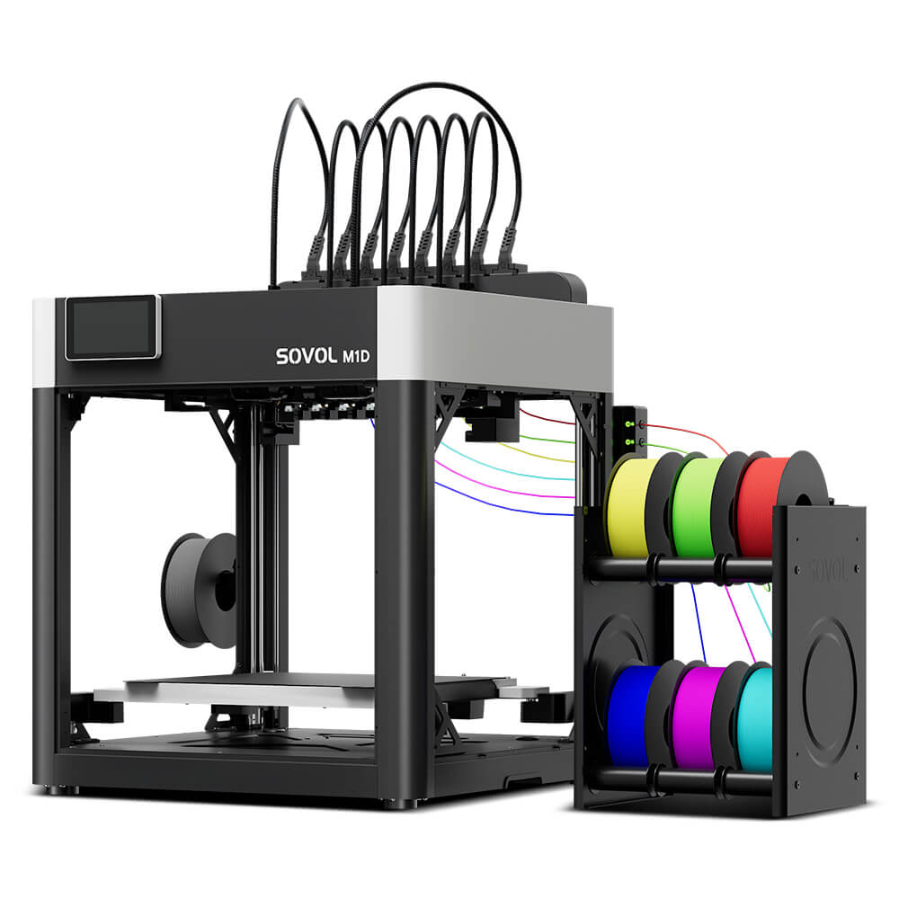
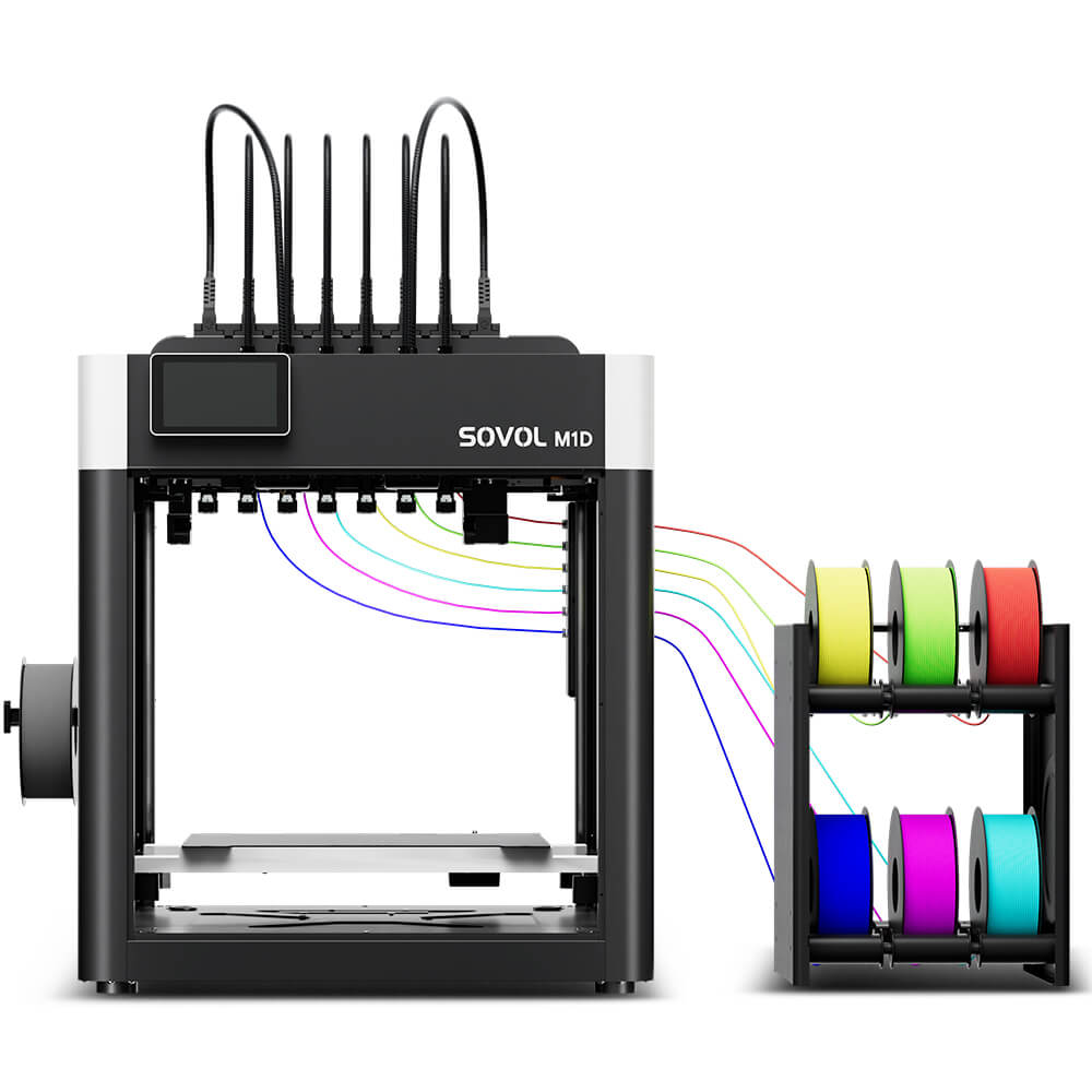
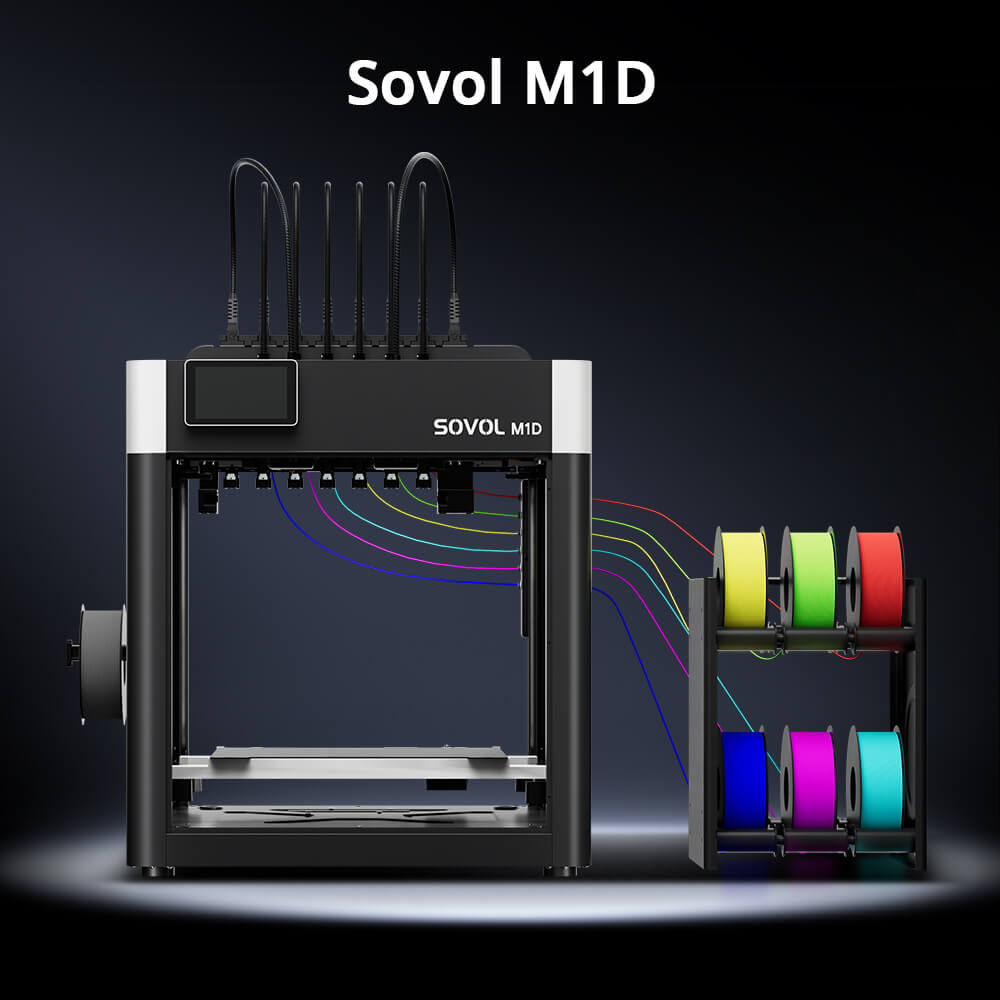
As one worked example, the Sovol M1D's official specifications describe a DualX 1+6 arrangement: one fixed toolhead plus six tool-changing toolheads, up to seven colors or materials, toolhead changes quoted at as little as 5 seconds, all seven toolheads heated independently, a 300 °C maximum nozzle, and OrcaSlicer as the listed default slicer. Those are official product figures, not independent test results. The available build area depends on the selected printing mode and toolhead configuration, so check the dimensions for the mode you plan to use.
Key Takeaway: Count your material changes before you slice. On a purge-based machine each change costs material and time; on a tool-changer it costs a swap.
Verify your result: you can state how many material changes your part needs and whether your printer's change method makes that cheap or expensive.
Step 5: Prepare the File in the Slicer and Verify Before the Full Print
By the end of this step you will have a sliced file whose tool assignments you have actually checked, plus a small test coupon that proves the interface works before you commit hours of filament.
Assign each body to a tool or filament, then confirm the mapping. Support and interface material assignments vary by slicer and printer profile, so defaults are not always what you expect. Always review the tool or filament assignment before slicing rather than trusting the defaults.
If you print without a MultiMaterialUnit, some slicers fall back to a manual filament change, which pauses mid-print for you to swap instead of running a tool change automatically. That pause is your swap, so the mapping has to be right the first time.
Pro Tip: Print the coupon with the real interface geometry, not a plain two-color square. A flat swatch proves nothing about a curved or interlocking boundary.
Then run the test-print loop: slice a coupon containing the actual interface and at least one material change, check the bond or the release, check the fit, and only then slice the full part. A clean boundary with no smearing and an interface that behaves as designed is usually a good signal to move ahead.
Common Mistakes to Avoid
A zero-clearance butt joint between two materials. Two flat faces pressed together with no overlap and no mechanical keying give the bond nothing to hold onto, so the joint fails at the layer line where the materials meet. The fix is to design an interlock: a dovetail, a through-hole, a rib, or a stepped overlap that lets the second material grab the first.
Assuming similar print temperatures mean similar chemistry. PLA and PETG may have overlapping printing temperatures, but similar temperatures do not guarantee strong interlayer adhesion. The result depends on the filament formulation, interface geometry, cooling, and print settings. Check the material pairing itself, not just the nozzle settings.
Leaving PVA or BVOH support exposed to air. These water-soluble filaments absorb moisture quickly, and once wet they deteriorate within a few months and soften at a much lower temperature than the dry spec suggests. Store them in a drybox and reseal the spool the moment you finish a print.
Alternating materials on every layer of a purge-based machine. Each swap costs purge filament and time, so a part that flips materials layer by layer multiplies both. Group each material into a contiguous region instead.
Slicing for a build volume your print mode does not provide. Multi-material modes can change the usable envelope, so a part that fits in single-toolhead mode may not fit once you switch. The available build area depends on the selected printing mode and toolhead configuration, so confirm the mode's actual dimensions before you commit to the model.
Results: What a Well-Designed Multi-Material Part Looks Like
If the design work was done, the result is visible before you measure anything. Run through four checks.
Boundary appearance. The color or material change should follow the region line you drew, with no smearing, stringing, or bleed across the interface. A fuzzy edge usually means the two regions overlapped in the model, not that the printer misbehaved.
Interface behavior under a hand test. Flex the part. A rigid-to-flexible interface designed to hold should stay bonded; one designed to release should separate cleanly at the boundary you set, not tear into the neighboring material.
Dimensional fit. The part should sit inside the build volume of the mode you sliced for, since that volume shrinks as toolheads are added to the job.
Material-change count. Compare the swaps your print actually made against the plan. Fewer means regions merged somewhere in the model.
Once a two-material part passes all four, the same region plan usually transfers to a family of related parts, and the proven interface geometry is what makes a third material a small step rather than a redesign.
If you want to see how a Sovol M1D handles those material changes in a tool-changing multi-material 3D printing workflow, the product page walks through the toolhead setup.
Frequently Asked Questions
How long does designing a multi-material part take compared with printing it?
Design usually runs longer than the print itself, and the split is uneven. Region planning, interface geometry and tool assignment in the slicer are where the hours go, because every material boundary has to be decided before the file is sliced. The print then runs largely unattended, so a part that takes an afternoon to design may finish overnight. Budget your time for the CAD and slicer work, not the machine time.
Can a single-nozzle printer do everything a tool-changer can?
Not in the same way. A single-nozzle machine can often reach a similar range of materials, but it pays for each switch with a purge, and the purge volume scales with how often colors or materials change. Tool-changing systems swap the whole hotend instead, so waste depends more on the number of changes than on the volume flushed at each one. If your part has many small color regions, that difference compounds quickly.
What should I do when the two materials will not stick at all?
Treat it as a design problem before a settings problem. Materials with very different chemistry, such as a rigid PLA body and a flexible TPU grip, need mechanical interlock rather than chemical bonding, so add dovetails, through-holes or a captured lip that holds the second material in place. If you want the interface to release on purpose, a breakaway or soluble support interface is the right choice instead of a bond.
How much filament does a purge-based workflow waste?
It depends on your change count and purge volume, and no independent measurement for the Sovol M1D was found, so treat any single figure with caution. The practical lever is reducing the number of tool changes per layer, since waste tends to track changes more than part size. Group same-material regions into one contiguous zone and the purge total often drops without touching a slicer setting.
Is PVA required, or will a breakaway interface do?
PVA earns its place when the support sits in a cavity you cannot reach, because it dissolves away in water after printing. A breakaway interface is cheaper and faster when the support is on an open overhang you can physically pull free. PVA is also moisture-sensitive, so it needs dry storage and a sealed spool between prints or the interface quality degrades.
Conclusion
You now have a part planned by region rather than by color, an interface designed to either hold or release, materials matched to the job each region does, and a small test coupon that proved the boundary before you committed a full print. That is the whole method, and it works because of one mechanism: most multi-material failures start at the material boundary, which means they are designed in, and anything designed in can be designed out.
The next step is to run the test-print loop on your own part. Start with the smallest coupon that reproduces your real interface, print it, flex it, and only then scale up to the full geometry. If you want a machine built around that workflow, the Sovol M1D uses a tool-changing system with independently heated toolheads, which keeps each material at its own temperature between swaps.