




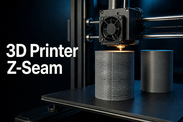
Whether you are printing a display prop, a functional enclosure, or a mechanical prototype, the Z-seam is one of the most persistent visual artifacts in desktop 3D printing. Because FDM extruders melt thermoplastic and lay down filament layer by layer, every closed perimeter loop must start somewhere and end somewhere. That inevitable intersection creates a visible mark.
Key Takeaway: The Z-seam is a natural byproduct of melt-extrusion physics, not a sign that your printer is broken. While you cannot alter the physical requirement that perimeter loops must start and stop, you can strategically control Z-seam placement, tune your slicer seam settings, and modify your model geometry to hide the seam completely on non-visible edges.
What Causes a Z-Seam?
Understanding why a 3D printing seam forms requires looking closely at what happens inside the hotend during layer transitions.
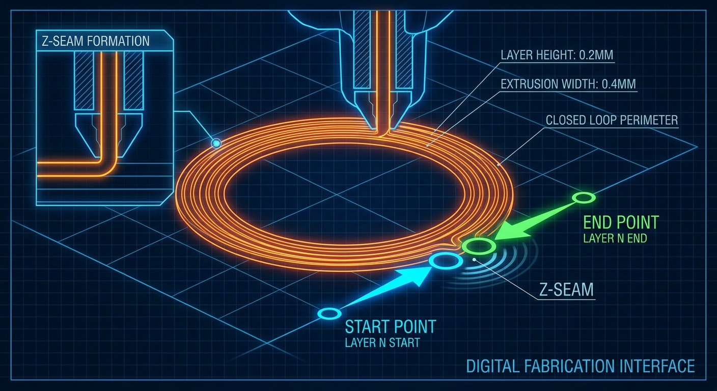
Layer Start and Stop Points
An FDM 3D printer creates solid objects by tracing 2D perimeter walls for each Z-height layer. To complete an outer perimeter loop, the nozzle must trace a 360-degree path and return to its starting coordinate. Where the beginning of the extrusion path joins the end, the two ends meet. Because molten plastic expands slightly under thermal pressure, this overlap creates a microscopic bump or dimple on the outer wall.
Retraction and Pressure Changes
Inside the hotend, molten filament stays under continuous hydraulic pressure while the extruder motor feeds material. When the nozzle reaches the end of an outer wall segment, the extruder rapidly reverses (retracts) to stop plastic flow before the nozzle lifts or travels to the next layer.
- At the stop point: Any residual pressure in the nozzle tip oozes out before retraction fully takes effect, leaving a tiny extra droplet of plastic (a seam bump).
- At the start point: When the extruder re-engages (un-retracts), there is a split-second delay before plastic begins flowing smoothly again, which can cause a tiny gap or pinhole.
Travel Moves and Restart Extrusion
After a perimeter is completed, the slicer may retract, wipe, and travel before starting the next perimeter or layer. Differences in nozzle pressure and oozing during this transition can create a bump or gap at the seam.
Distinguishing the Z-Seam from Other Surface Defects
Before adjusting slicer settings to reduce Z-seam visibility, confirm that the mark on your part is actually a seam and not another common printing issue:
- Z-Seam: A distinct line, ridge, or uniform series of dots occurring at the layer start/stop boundaries on wall perimeters.
- Blobs / Zits: Random surface pimples caused by wet filament expanding steam, incorrect extrusion flow multiplier, or thermal fluctuation during long print runs.
- Stringing: Fine spiderweb-like plastic threads stretching across open air gaps between separate parts of a model during travel moves.
- Under-Extrusion: Weak, spongy, or missing wall layers throughout entire sections caused by partial hotend clogs or insufficient extruder tension.
- Layer Shift: A hard horizontal misalignment where the upper half of the entire print steps sideways due to loose drive belts or stepper motor skips.
Main Z-Seam Placement Options
Modern slicing software offers multiple algorithms to dictate where layer start points occur. Exact menu names and options vary between slicers like OrcaSlicer, PrusaSlicer, Ultimaker Cura, and Bambu Studio.
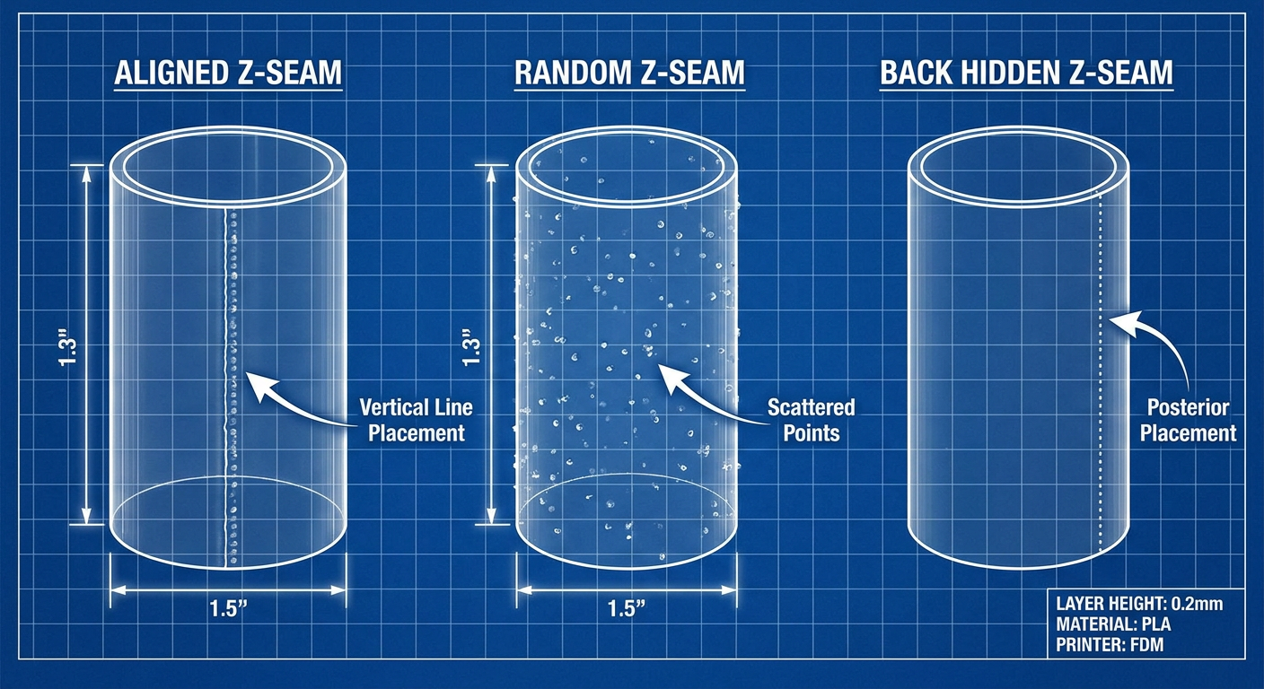
1. Aligned or Back Seam
- Slicer Support: Aligned or Back in OrcaSlicer, PrusaSlicer, and Bambu Studio; User Specified / Back in Cura.
- How it works: The slicer calculates a single coordinate axis or build plate direction and stacks layer start points directly above one another.
- Best for: Flat-backed display pieces, wall-mounted brackets, or objects with an obvious rear side that remains hidden after installation.
2. Nearest Seam
- Slicer Support: Nearest or Shortest in OrcaSlicer, PrusaSlicer, and Cura.
- How it works: The slicer places the seam near where the nozzle finished its previous stop position, minimizing non-printing travel distance across the model.
- Best for: Minimizing travel moves and shortening total print time on complex models with multiple separate islands.
3. Random Seam
- Slicer Support: Random in OrcaSlicer, PrusaSlicer, Cura, and Bambu Studio.
- How it works: The slicer selects a new starting coordinate along the perimeter for every layer, scattering start points across the surface.
- Best for: Cylinders and organic shapes where a single vertical seam line would stand out.
- Trade-off: While Random seam avoids a continuous vertical line, it scatters tiny surface zits over the entire part. This trade-off means it may not be suitable for models requiring a smooth, pristine surface finish.
4. Corner Alignment / Sharpest Corner
- Slicer Support: Corner-hiding algorithms integrated into Aligned or Smart modes (or dedicated corner options depending on slicer version).
- How it works: The slicer analyzes the 3D mesh geometry and automatically places layer start points along tight interior or exterior corners.
- Best for: Cubes, enclosures, brackets, and geometric shapes with sharp edges. The vertex naturally disguises the start/stop swelling.
5. User-Painted Seam Placement & Scarf Seams
- Slicer Support: Seam Painting Brush in OrcaSlicer, PrusaSlicer, and Bambu Studio; Scarf Seam (Ramped/Beveled Seams) in OrcaSlicer and Cura 5.9+.
- How it works: Seam painting lets you manually paint a zone directly on the 3D model canvas to enforce or block seam placement. Scarf seams go further by feathering (sloping) the extrusion end over the start point like a lap joint.
- Realistic Expectations: Scarf seams can significantly reduce visible seam defects. However, results still depend on your model geometry, material, and slicer version, and scarf seams can be less effective on sharp corners or overhang regions.
How to Choose the Best Seam Location
Relying on default slicer auto-placement often leaves seams on prominent, smooth faces. Choosing the optimal Z-seam placement requires matching your model's geometry with its intended real-world orientation.
1. Place Seams on the Least Visible Side
Determine which face of the printed part will be hidden from view during normal use. For a desktop drawer organizer, force the seam onto the rear exterior wall or inside an interior corner. For a wall mount, align the seam along the side that flush-mounts against the wall.
2. Use Corners, Recessed Areas, and Natural Edges
Sharp corners are the effective hiding spots for 3D printer Z-seam artifacts. When a nozzle turns a sharp corner, the natural change in motion direction masks the tiny extrusion swell. Look for vertical ridges, interior structural pockets, or decorative panel lines in your model mesh where a seam can blend seamlessly into existing surface features.
3. Avoid Seams on Curved Front Surfaces
Sweeping curved geometry—such as the front hood of a scale model, a vase, or a cylinder—reflects light continuously across its surface. A vertical seam line on a smooth radius immediately catches light and draws the eye. Never use Aligned seam settings on round front-facing geometry without steering the seam coordinates toward the back.
4. Rotate the Model Before Changing Complex Settings
Before diving deep into advanced slicer parameters, try rotating your model 90 or 180 degrees on the digital build plate. Because many slicers default to placing back seams along the rear Y-axis (Y-max), simply rotating a helmet or figure so its back faces the rear of the build plate instantly pushes the seam off the face and onto the hidden rear hair or collar line.
5. Use Seam Painting for Detailed or Cosmetic Models
When printing intricate miniatures, organic sculptures, or multi-faceted prop helmets, automatic corner detection can fail. Use the manual seam painting brush in OrcaSlicer or PrusaSlicer to draw a clean seam path down an inconspicuous fold in clothing, an armor plate seam, or a hidden rear shadow line.
Slicer Settings That Can Reduce Seam Visibility
Once you have positioned the seam in the least noticeable location, fine-tuning your slicer seam settings helps shrink the physical size of the start/stop mark.
Important: The following slicer parameters are highly dependent on your specific 3D printer hardware, hotend type, nozzle diameter, and filament material. Treat these values as baseline starting points for testing, not universal magic numbers.
1. Retraction Settings
Retraction pulls filament back from the hotend melt zone right as a perimeter ends.
- Direct Drive Extruders: Typical retraction distance ranges from 0.4 mm to 1.2 mm at speeds of 30–50 mm/s as baseline guides.
- Bowden Tube Extruders: Typical retraction distance ranges from 2.0 mm to 6.0 mm at speeds of 40–60 mm/s as baseline guides.
- Tuning Tip: Retraction settings should be tuned based on your specific printer, nozzle, and material setup. If you see a swollen bump at the seam, fine-tune retraction distance in small 0.1 mm increments. If you see a hollow gap or pit, your retraction distance may be too long, drawing air into the nozzle.
2. Wipe While Retracting (Wipe Distance)
Wiping keeps the nozzle moving along the inner wall path for a short distance (typically 0.2 mm to 1.0 mm) while simultaneously executing a retraction. This spreads residual nozzle tip pressure inside the perimeter shell rather than letting plastic ooze onto the visible exterior surface.
3. Pressure Advance (Klipper) / Linear Advance (Marlin)
Firmware-level pressure control dynamically adjusts extruder motor movement during rapid acceleration and deceleration phases. Standard extruders tend to over-extrude at the end of a line (as the toolhead slows down) and under-extrude at the beginning of a line (as the toolhead speeds up).
Properly calibrated Pressure Advance neutralizes these pressure spikes, flattening seam bumps and filling start-point gaps. Review our comprehensive Klipper Pressure Advance tuning guide to calculate exact K-factor values for your specific toolhead setup.
4. Outer Wall Speed vs. Travel Speed
Print head speed directly impacts pressure stability in the nozzle melt chamber:
- Outer Wall Speed: Moderate outer wall speeds (e.g., 30 to 60 mm/s) allow plastic flow to stabilize, producing uniform wall thickness and reducing seam bulge.
- Travel Speed: A fast travel speed reduces the duration available for residual plastic to ooze during travel moves. Always adjust travel speed according to your printer's motion hardware limits and filament profile, verifying stability with small test prints. Learn more about balancing motion parameters in our article on optimizing 3D print speed versus surface quality.
5. Coasting (Legacy Slicers)
Coasting stops active filament extrusion slightly before the end of a perimeter loop (e.g., stopping extrusion 0.2 mm early), using the remaining hotend pressure to finish tracing the wall segment. While useful in older Marlin setups running Cura, modern Klipper-based CoreXY printers perform far better using Pressure Advance instead of coasting.
6. Temperature and Flow Calibration
Printing at excessively high temperatures lowers plastic viscosity, causing severe oozing at layer start points. Similarly, general over-extrusion forces excess plastic out of the nozzle tip across the entire wall, making seams balloon outward. Perform a precise 3D printer flow rate calibration to ensure your wall thickness matches your slicer's line width expectations.
Model Design Tips: Hiding Seams in CAD
If you design your own 3D models in CAD software (such as Fusion 360, Onshape, or SolidWorks), you can incorporate structural geometry features that give slicers natural, hidden places to deposit seams.
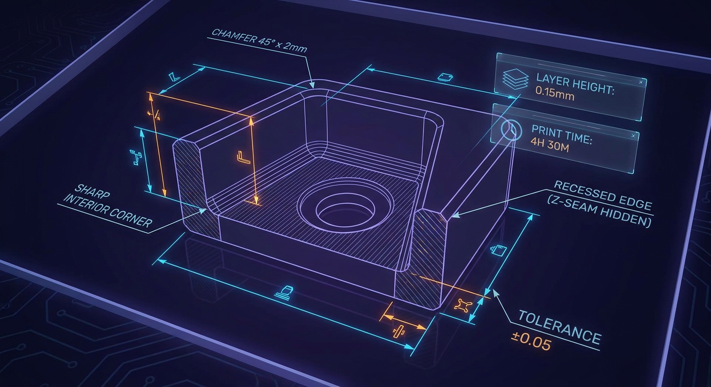
1. Add Chamfers or Recessed Vertical Features
Adding a small vertical chamfer or bevel (such as 0.5 mm, depending on your nozzle diameter and layer height) to an otherwise flat wall creates a subtle interior corner angle. Slicers set to hide seams in corners will automatically select this recessed crease for layer transitions, burying the seam inside the geometry recess.
2. Place Seams on Interior Corners or Hidden Structural Edges
When designing functional enclosures, electronic boxes, or mechanical housings, orient structural ribs, screw bosses, or mounting tabs on the inside walls. The intersection where an internal rib meets an outer wall provides a natural high-angle vertex where the slicer can hide the start point without affecting outer cosmetic walls.
3. Maintain Consistent Wall Thickness
Avoid abrupt transitions between thick and thin wall sections along exterior shells. Sudden changes in wall geometry alter hotend flow rate demand mid-perimeter, creating localized pressure spikes that make nearby Z-seams bulge more noticeably.
4. Break Up Large Curved Front Surfaces
If your part features a wide, sweeping curved front face, consider adding subtle vertical panel lines, textured grip ribs, or decorative fluting. These vertical aesthetic grooves break up continuous light reflection and provide designated vertical channels for seam alignment.
5. Design a Sacrificial or Cosmetic Breakaway Tab
For high-precision cosmetic prototypes where no exterior surface mark is acceptable, model a small breakaway tab attached to a non-critical edge (sized proportionally to your nozzle width and layer height, e.g., 0.4 mm as a starting point). Force the slicer seam onto this sacrificial feature using seam painting, then snip or sand off the tab after printing is complete.
Common Z-Seam Problems and Fixes
Use this diagnostic troubleshooting guide to identify the root cause of your seam defects and apply the correct slicer or CAD remedy:
|
Observed Defect |
Likely Root Cause |
Practical Slicer or CAD Adjustment |
|---|---|---|
|
Small bumps or zits at every layer start |
Excessive hotend pressure at perimeter end; insufficient retraction or wipe. |
Enable Wipe While Retracting (0.4–0.8 mm); increase retraction distance in 0.1 mm increments; calibrate Klipper Pressure Advance. |
|
Gaps, holes, or crater pits at the seam |
Over-retraction pulling air into nozzle; excessive coasting distance. |
Reduce retraction distance; disable Coasting if running Pressure Advance; add 0.1 mm Extra Prime Amount upon un-retract. |
|
Random pimples scattered around the entire model |
Seam alignment set to Random; wet filament expanding. |
Change seam position to Aligned, Back, or Sharpest Corner; dry filament in a dedicated filament dryer. |
|
Seam line appearing on the prominent front face |
Model oriented incorrectly relative to slicer rear axis vector. |
Rotate model 180° on digital build plate; use manual Seam Painting brush to move seam to back. |
|
Seam mark combined with fine stringing |
Printing temperature too high; retraction speed too slow. |
Lower printing temperature by 5–10 °C; increase travel speed to 250+ mm/s; tune retraction speed. |
|
Seam mark combined with ringing or ghosting |
Mechanical vibration at toolhead direction changes; excessive speed. |
Lower outer wall speed (30–50 mm/s); calibrate Klipper Input Shaping; tighten motion belts and carriage hardware. |
How to Test and Compare Z-Seam Settings
Tuning slicer settings without systematic testing leads to wasted filament and inconclusive results. Follow this structured calibration workflow to isolate and hide Z-seam defects effectively.
- Select a Standardized Test Model: Print a small shape that highlights seam behavior, such as a 30 mm calibration cube (for sharp corner hiding) or a 40 mm hollow cylinder (for curved surface testing).
- Change Only One Parameter at a Time: Adjust a single variable per test print—such as changing retraction distance from 0.6 mm to 0.8 mm while keeping speed, flow, and temperature identical. Label each printed test piece with a permanent marker.
- Evaluate Multiple Quality Metrics: Inspect test parts for surface uniformity, dimensional accuracy, total print time, and structural layer bonding.
- Validate Settings Across Different Materials: Settings tuned for PLA will not automatically produce pristine seams on PETG or TPU. Re-run your calibration cylinder test whenever switching material families.
Z-Seam Optimization Tips for Sovol Printers
Sovol 3D printers are engineered to give makers, modders, and functional builders open-source control over their hardware and firmware. Applying seam optimization principles across different Sovol machine architectures unlocks exceptional surface finish quality.
High-Speed CoreXY Printing: Sovol SV08 and SV08 MAX
For high-speed CoreXY machines like the Sovol SV08 CoreXY printer (featuring a 350×350×345 mm build volume, Klipper firmware, planetary direct drive extrusion, and official maximum hardware speeds up to 700 mm/s) and the large-scale Sovol SV08 MAX (500×500×500 mm build volume with official max hardware acceleration up to 40,000 mm/s² and max volumetric flow up to 50 mm³/s):
Note: Maximum hardware capabilities (such as 700 mm/s speed or 50 mm³/s flow) reflect printer hardware limits, not recommended printing parameters for optimal Z-seam quality. Surface quality tuning typically requires moderate printing speeds.
- Leverage Klipper Pressure Advance: During rapid direction and speed changes, high-flow toolheads build internal melt pressure. Calibrating Pressure Advance in Klipper is the single most effective way to eliminate seam bulges on the SV08 series.
- Short Direct Drive Retractions: Because the SV08 direct drive planetary extruder features a short, rigid filament path, keep retraction distances small (0.4 mm to 0.8 mm). Avoid long Bowden-style retractions, which can pull hot plastic above the heatbreak and cause clogs.
- Utilize OrcaSlicer Scarf Seams: Pair your SV08 Klipper profile with OrcaSlicer's Scarf Seam feature. The combination of Klipper pressure management and feathered scarf seam overlaps produces clean exterior perimeters even on large-scale prints.
Compact Desktop Performance: Sovol Zero
For compact desktop models like the Sovol Zero:
- Keep outer wall speeds moderate (40 to 60 mm/s) to maintain stable flow pressure.
- Set Z Seam Alignment to Sharpest Corner for geometric prints, or use Seam Painting to manually route seams along rear structural edges.
Setting Realistic Expectations
Even on high-performance CoreXY machines, FDM technology physically melts and deposits continuous tracks of thermoplastic. While proper calibration, model orientation, and advanced slicer settings like scarf seams will dramatically hide the Z-seam from view, no desktop FDM printer can eliminate the physical layer start/stop boundary entirely. Understanding this balance helps you achieve professional, eye-catching surface quality on every project.
Conclusion
Achieving smooth, clean visible surfaces on your FDM prints does not require secret magic—it requires a coordinated approach combining smart CAD modeling, intentional model orientation, and calibrated slicer settings.
To minimize Z-seam visibility on your next 3D printing project:
- Orient your part strategically on the build plate to push layer start points onto non-cosmetic or hidden rear faces.
- Leverage natural geometry by using Sharpest Corner placement, adding chamfers in CAD, or drawing custom seam paths with seam painting.
- Calibrate your extruder motion by fine-tuning retraction distance, enabling outer wall wipe, and calibrating Klipper Pressure Advance.
- Test systematically using simple calibration cylinders before launching long, material-intensive prints.
By mastering how seam placement, model geometry, and slicer settings interact, you can consistently produce FDM prints with clean, professional surface finishes across all your maker creations.