


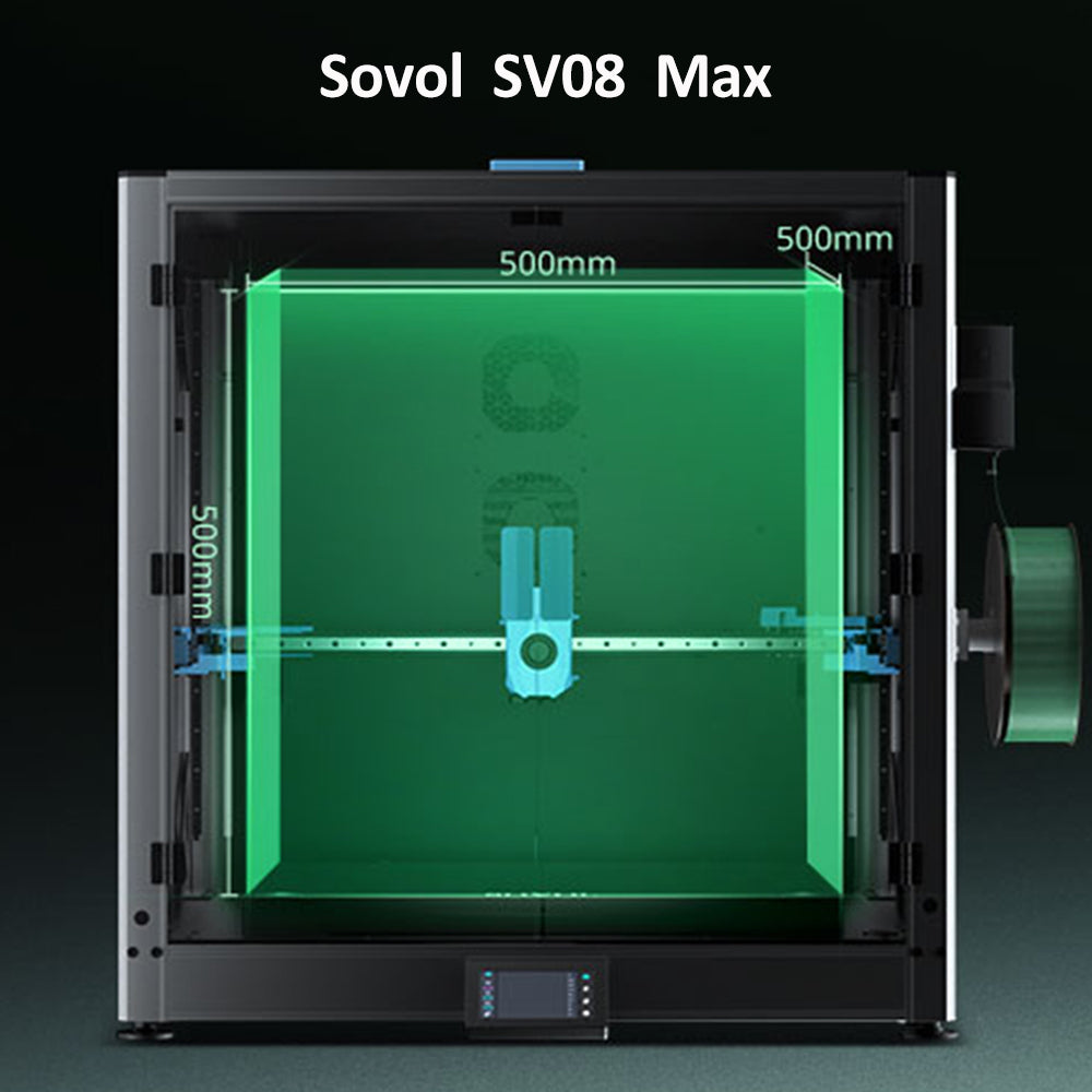




Bed mesh calibration probes the build surface at multiple points so the firmware can build a height map and raise or lower the nozzle as it moves across the bed. That fixes uneven first layers caused by small height differences across the plate — one area too close, another too far. It doesn't replace mechanical tramming, a correct Z-offset, or a clean plate, and it can't fix a loose gantry or a skewed axis.
Quick Answer
The printer scans the bed at several defined points, stores the heights as a grid, and while printing adjusts nozzle height to follow that measured shape. A slightly bowed plate or a removable sheet that doesn't sit perfectly flat will otherwise leave one region of the first layer squished and another with gaps.
It is not a cure-all. A mesh approximates the bed in software, so it can't fix a loose gantry, a dirty plate, a wrong Z-offset, or an unreliable probe. Klipper's documentation puts it bluntly: software correction "can only approximate the shape of the bed" and "cannot compensate for mechanical and electrical issues."
Not all FDM printers include a probe or mesh-capable firmware, and menu paths and G-code commands vary between Marlin, Klipper, and vendor firmware. Treat the steps below as the underlying logic, then follow your manufacturer's exact sequence.
Bed Leveling vs Bed Mesh vs Z-Offset: Three Different Jobs
These three procedures are often lumped together as "leveling," but they answer different questions. Keeping them separate is the fastest way to stop chasing the wrong problem.
Mechanical leveling (tramming)
Tramming physically squares the bed to the plane the nozzle moves in, usually by turning screws or knobs at the corners until the nozzle-to-bed gap matches at each adjustment point. Marlin's tramming documentation describes the goal as making the bed surface parallel to the nozzle's plane "so the gap between nozzle and bed is the same everywhere."
What it cannot do: tramming makes the corners agree, but as the same documentation notes, it "can't change the shape of the plate between them." A bowed plate can have perfectly matched corners.
Bed mesh calibration
A mesh measures height variation across the surface and lets firmware compensate in software. It does not move the bed; it teaches the printer what shape to follow. A mesh cannot correct a skewed axis or a probe that reports inconsistently, and it is only as good as the mechanical condition underneath it.
Z-offset adjustment
Z-offset sets the overall nozzle-to-bed gap for the first layer. Changing it shifts the entire first layer up or down — it does not tilt or reshape anything. If the first layer is too close everywhere, Z-offset is the tool; if it is too close on one side only, Z-offset will not fix it.
Klipper and Marlin document these as separate procedures with separate commands, though some printers combine or automate parts of them. On machines with automatic Z-offset systems, the printer may handle one or more of these steps itself — check what yours actually does before adjusting anything manually.
Comparison Table: Purpose, What It Changes, and When You Need It
|
Method |
Purpose |
What it measures or changes |
When you may need it |
|---|---|---|---|
|
Mechanical leveling (tramming) |
Make the bed parallel to the nozzle's plane |
Physical gap at the adjustment points, changed with screws or knobs |
After assembly, moving the printer, or when one side prints differently from the other |
|
Bed mesh calibration |
Let firmware follow the bed's actual shape |
Height at multiple points across the surface, stored as a grid |
When the plate is not perfectly flat, or first-layer quality varies by location |
|
Z-offset adjustment |
Set the overall first-layer gap |
The nozzle-to-bed distance for the whole first layer |
When the first layer is uniformly too close or too far |
Some printers automate one or more of these steps. The table describes the underlying job, not a specific menu item or command name.
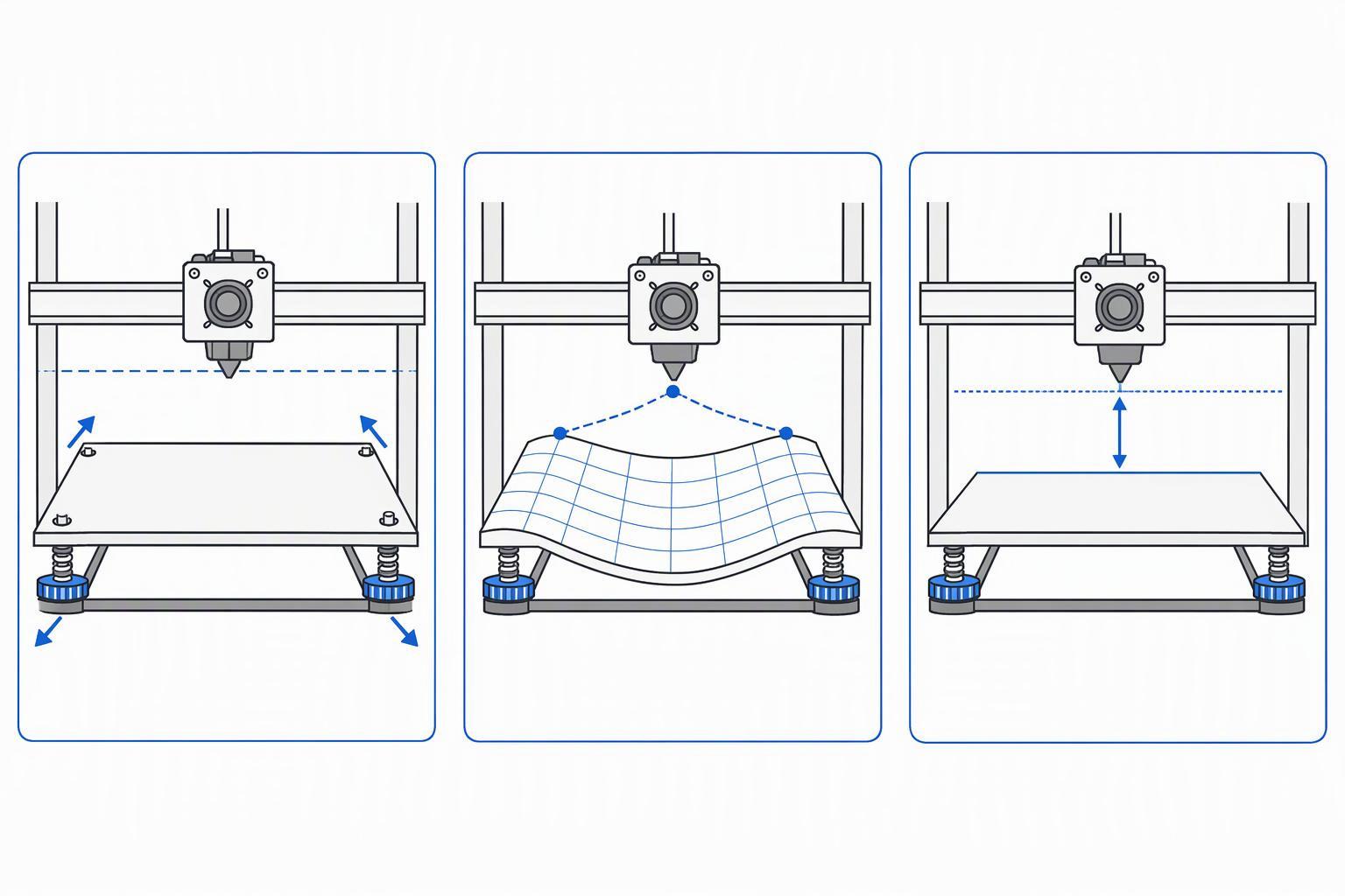
Tramming squares the bed to the nozzle plane, the mesh follows the plate's shape, and Z-offset sets the overall first-layer gap.
How a Printer Builds a Bed-Height Map
The general sequence is consistent across mesh-capable printers, even though the details are not.
The printer moves a probe or sensor to defined points across the bed and records the trigger height or measured distance at each. Firmware stores those values as a grid or mesh. During printing, it looks up the values near the nozzle's position and adjusts Z so the nozzle follows the measured surface rather than a flat plane.
The sensor type changes how this works. Physical touch probes contact the surface at each point. Inductive and capacitive sensors trigger without contact and can be affected by surface material, nearby metal, and temperature. Eddy-current sensors return a proportional distance value, which allows some systems to scan continuously across the bed instead of stopping at discrete points — the RepRap wiki's probe overview describes this difference. Some printers combine more than one sensing method, so check your printer's documentation to understand how each sensor is used.
Point count, probing area, probing speed, and the commands used all depend on the printer, firmware, and sensor. Klipper's Bed Mesh documentation exposes these as configuration parameters rather than fixed rules, and Marlin's mesh bed leveling and auto bed leveling pages describe several different grid systems. Use your manufacturer's documented procedure rather than a generic recipe.
The practical consequence: the mesh can only be as accurate as the mechanical condition and probe repeatability beneath it. A precise map of a loose bed is still a map of a loose bed.
Why Your First Layer Is Uneven: Common Causes
An uneven first layer usually has more than one contributor. Match what you see to the list below, then fix causes in roughly this order — mechanical and surface issues first, compensation last.
Build plate contamination. Oils from fingerprints, dust, and residue from previous prints change adhesion locally. What you would see: poor sticking in patches that do not match the mesh pattern, or filament that beads up in one region. Clean according to your plate manufacturer's guidance — some surfaces tolerate solvents that damage others.
Incorrect Z-offset. What you would see: the whole first layer too squished (rough, translucent, ridges between lines) or too loose (rounded lines, gaps, poor bonding) everywhere on the bed. Adjust Z-offset, not the mesh.
A plate or gantry that is not positioned correctly. What you would see: one side consistently different from the other. On printers with two Z motors, one side of the gantry can sit lower; Marlin's tramming documentation advises fixing a tilted gantry before tramming the bed, otherwise you tram to a crooked reference.
Temperature changes. Bed and nozzle geometry shift as they heat. Klipper's bed leveling page notes that the nozzle's position relative to the bed changes with thermal expansion when heated. A mesh taken cold may not match a hot print. Probe under the conditions your manufacturer specifies.
A damaged or replaced build surface. Dents, tears, and scratches create local height errors. A new or flipped sheet has a different thickness and surface than the one the mesh was taken on. What you would see: a problem that appeared right after changing the sheet.
Outdated or incorrect calibration data. A saved mesh from before a hardware change, or a mesh that was measured but never activated. Marlin's documentation lists several ways a stored mesh can be lost or ignored — not saved, discarded after a grid-size change, or disabled by homing until re-enabled in start G-code.
Mechanical looseness or obstruction. Loose eccentric nuts, low belt tension, a wobbly plate mount, or a stray piece of filament under the sheet. What you would see: readings or first-layer results that change from print to print without any setting change.
When several causes coexist, fixing the mechanical one usually beats compensating for it. If you want a deeper walkthrough of first-layer adhesion, see Sovol's guide to fixing a first layer that will not stick.
A General Bed Mesh Calibration Workflow
Command names and menu paths differ between Marlin, Klipper, and vendor firmware. A common workflow is to check mechanical alignment first, run the mesh, and then adjust the Z-offset with the mesh active. The exact sequence depends on the printer and firmware, so follow the manufacturer's instructions.
- Clean and inspect the build plate. Remove debris, filament fragments, and oils. Check for damage.
- Check mechanical condition. Frame, gantry, belts, screws, plate mounts, and anything under the sheet. Fix what is loose before measuring.
- Tram if your printer allows it. Follow the manufacturer's procedure for the corner screws or the assisted tramming routine. Skip this if your machine has no manual adjustment.
- Warm the printer according to the manufacturer's guidance when appropriate. Some procedures specify probing at print temperature; others do not. Follow yours.
- Home the printer. Most mesh routines require homed axes first.
- Run the available mesh calibration process. Use the menu item or command your firmware documents.
- Save or activate the mesh only if supported. Some systems require an explicit save, an activation command, or a line in the slicer's start G-code — Marlin's documentation notes that homing can turn leveling off, so the mesh may need re-enabling each print.
- Set Z-offset with the mesh active. Adjust in small steps and confirm with a test print rather than a number copied from a forum.
- Print a first-layer test pattern that covers the areas you actually print on, not just the center.
- Change one thing at a time and re-test. Changing Z-offset and the mesh together makes it impossible to tell which helped.
If you are setting up a new machine, Sovol's SV08 preparation guide walks through the assembly and calibration sequence, and the beginner calibration guide covers the wider set of checks around it.
How to Read a Bed Mesh Height Map
A mesh visualization is a diagnostic picture, not a score. The useful questions are whether the pattern is stable between runs and whether it matches what the first layer actually does.
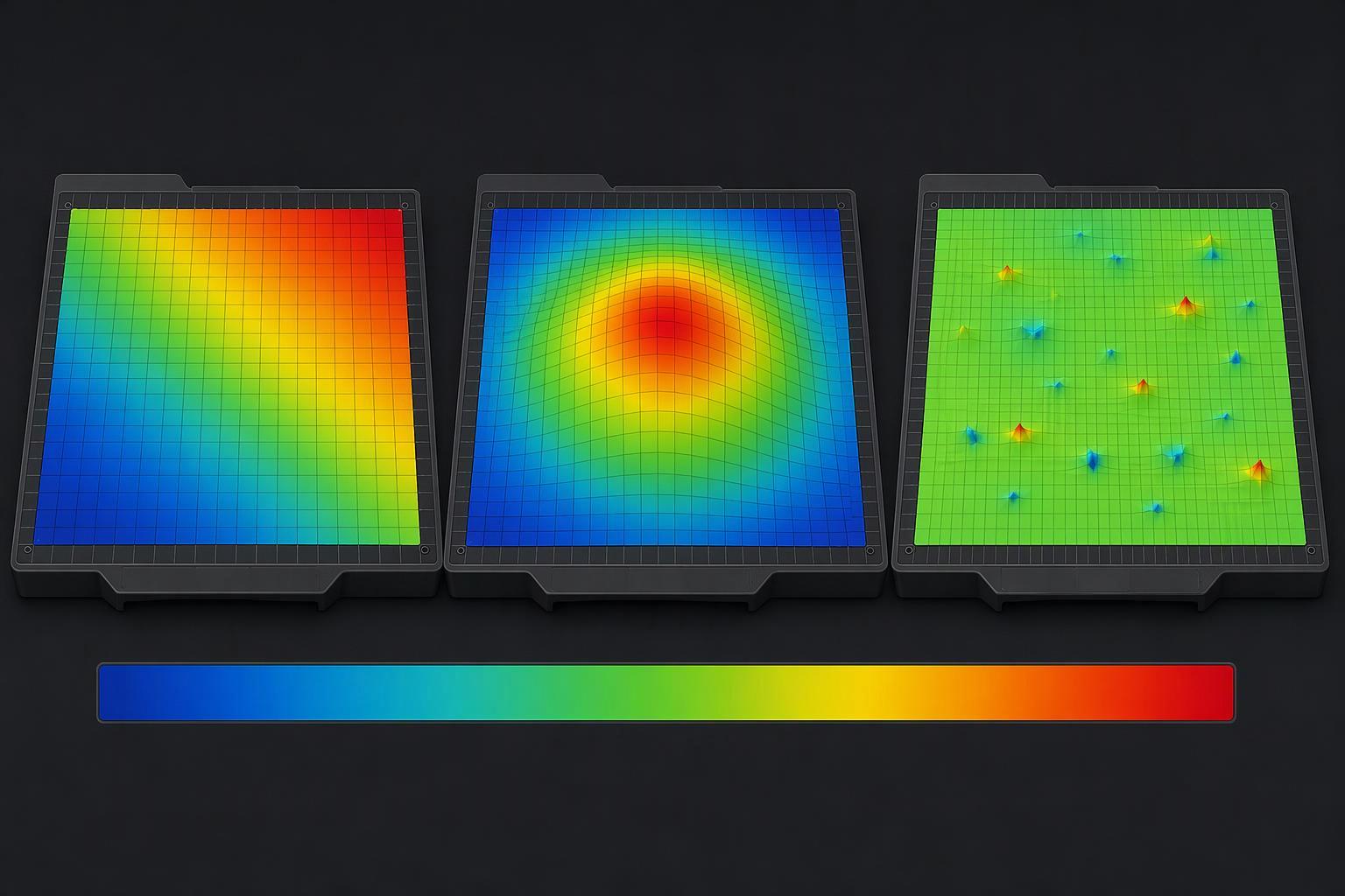
Typical patterns: a diagonal tilt, a raised center, and scattered random spikes.
One side consistently higher or lower. A consistent height difference from one side to the other may indicate bed tilt, gantry misalignment, or an unevenly seated build plate. Check the mechanical adjustment before re-probing.
A gradual slope across the bed. Also tilt or a mounting issue, sometimes a plate that sits unevenly on its supports. If tramming does not reduce it, look at how the plate is seated.
A raised center or raised edges. This may indicate the shape of the build plate or excessive mounting tension rather than simple tilt. A sheet clamped too tightly can bow; so can a worn surface. Tramming won't change it, and a mesh can only approximate it.
Random spikes or inconsistent readings. Isolated high or low points that move between runs suggest probe noise, debris under the sheet, loose hardware, or electrical interference. Re-probe after cleaning and check that the readings repeat before trusting the map.
There is no single acceptable range that applies to every printer, and no universal "good" number to chase. What matters is that the map is repeatable and that the first layer confirms it. If the numbers look acceptable but the print does not, trust the print and investigate the causes in the next section.
Troubleshooting Table: Matching Symptoms to Likely Fixes
|
Symptom |
Likely cause |
First thing to check |
|---|---|---|
|
First layer uniformly too close or too far |
Z-offset |
Adjust Z-offset in small steps; leave the mesh alone |
|
One side prints differently from the other |
Bed tilt or a tilted gantry |
Tram the bed; on dual-Z machines, check gantry alignment first |
|
Only certain areas have poor adhesion |
Contamination, plate damage, or a local mesh error |
Clean the plate, inspect for damage, re-probe |
|
The mesh changes between prints |
Loose hardware, probe repeatability, or temperature differences |
Check mounts and belts; probe under consistent conditions |
|
Calibration succeeds but the first layer is still uneven |
Mesh not saved or activated, wrong Z-offset, or a mechanical fault |
Confirm the mesh is active in the start G-code, then re-check Z-offset |
If the first layer still misbehaves, the print-quality calibration guide covers flow and extrusion settings that can mimic leveling problems.
When Should You Recalibrate?
Recalibrate when something that affects the measurement has changed, not on a fixed schedule:
- After moving the printer or bumping the frame
- After changing, flipping, or replacing the build plate or sheet
- After maintenance that touched the gantry, belts, or plate mounts
- After changing relevant hardware — nozzle, probe, hotend, or plate
- When you notice a persistent change in first-layer behavior that cleaning and Z-offset do not explain
Some printers re-probe automatically before each print; others rely on a saved mesh until you replace it. The practical answer therefore depends on the machine, and there is no universal "every X prints" rule worth applying across models.
FAQ
Is bed mesh the same as bed leveling? No. Leveling or tramming is a mechanical alignment of the bed to the nozzle's plane. A mesh is software compensation for height variation across the surface.
Does bed mesh calibration fix an incorrect Z-offset? No. It adjusts for variation across the bed, not the overall first-layer gap. Set Z-offset separately, with the mesh active.
Do I need to run mesh calibration before every print? It depends on the printer. Some probe automatically at the start of a print; others use a saved mesh. Follow the manufacturer's guidance and re-run when conditions change.
Why does my bed mesh change after the printer heats up? Thermal expansion shifts the nozzle-to-bed relationship and can move the plate. Probe under the conditions your manufacturer specifies so the mesh matches your printing conditions.
Can bed mesh compensate for a warped build plate? Partially. It approximates the shape within limits, but it cannot correct severe warping, a skewed axis, or mechanical faults, and results degrade as the deviation grows. If you suspect the plate itself, Sovol's guide to diagnosing a warped bed walks through the practical checks.
Final Thoughts
Bed mesh calibration is one step in a sequence, not a standalone fix. It works best on a mechanically sound printer with a clean surface and a correct Z-offset, and it cannot substitute for any of them. When a first layer goes wrong, work from the mechanical causes outward: clean, check, tram, then mesh, then Z-offset. That order saves time and tells you which change actually made the difference.