

Two of those settings are separate decisions that people often merge into one: how much infill you use (density) and what shape it takes (pattern). Neither one on its own decides whether a part is strong, light, or quick to print. By the end of this guide you will know how density and pattern each change strength, weight, print time, and surface quality, and how to confirm the result in your slicer before you commit filament.
Quick Answers: Infill Density, Patterns, and How to Choose
What does infill density mean? Infill density is the percentage of the model's internal volume that the slicer fills with sparse structure. At 20%, roughly a fifth of that interior space receives infill lines; the rest stays hollow. It is a measure of how much material goes inside — not a strength rating. A 40% part is not "twice as strong" as a 20% part in any predictable way.
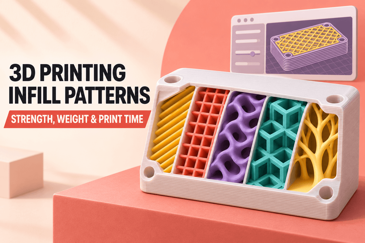
How do infill patterns differ? At the same density, patterns differ in the geometry of the internal paths: whether lines cross within a layer, whether the structure repeats in all three dimensions, and whether the paths follow the walls. That geometry changes how load travels through the interior, how much material the pattern actually uses, and how the nozzle moves.
Does higher infill always make a part better? No. More infill adds material, weight, and print time, and its effect on strength depends on wall count, model geometry, material, nozzle size, layer height, and print orientation. Past a certain point the returns shrink while the costs keep climbing.
How do I choose infill for decorative, functional, and lightweight parts? Use the table below as a first test, not a rule. These ranges are examples for initial testing, not universal settings — the right choice depends on geometry, wall count, material, orientation, nozzle, layer height, and the required load.
|
Part type |
Example starting range for testing |
Pattern family to try first |
What you are optimizing |
|---|---|---|---|
|
Decorative models |
5–15% |
Lines, lightning, or another low-material pattern |
Filament use and print time; internal strength rarely matters |
|
Functional parts |
20–40% |
Gyroid, cubic, or triangles |
Stiffness and load distribution, balanced against weight |
|
Lightweight or large parts |
5–15% |
Gyroid, adaptive cubic, or lightning |
Weight and material savings while keeping top surfaces supported |
A thin decorative figure and a large cosplay shell can both be "decorative" and still need very different settings.
Density, Pattern, Walls, and Shells: Four Settings People Confuse

Four settings get mixed up constantly, and every recommendation later in this article depends on keeping them apart.
- Infill density — the percentage of internal volume filled with sparse structure. It controls how much material sits inside the part.
- Infill pattern — the geometry of those internal paths at a given density. It controls how the interior material is arranged.
- Wall count (perimeters) — the number of solid outlines printed around the outside of each layer. On most parts they carry a large share of bending and tensile load.
- Top and bottom shell thickness — the solid layers that close the top and bottom of the part, and what you see as the top surface.
Walls and shells are solid; infill is sparse. Raising infill does not compensate for thin walls, and adding walls does not fix a top surface sagging over a wide empty gap. Each setting solves a different problem.
Common Infill Patterns Compared

Pattern names, behavior, and availability vary between slicers, so match patterns by description rather than by label. Some slicers limit which infill patterns can be used at very high density, and the available options may vary by software and version. Check the slicer preview after changing the density.
- Lines / rectilinear — parallel lines in each layer, with the direction alternating between layers. Simple and fast, with no crossings within a layer.
- Grid — two sets of perpendicular lines in the same layer. The paths cross, so material accumulates at intersections.
- Triangles — a triangle-based grid printed in three directions. May provide higher in-plane stiffness, depending on the model and slicer implementation.
- Gyroid — a smooth, continuous 3D wave that repeats in all three axes. It does not self-intersect within a layer and can provide a more balanced internal structure for loads from different directions.
- Cubic — cubes oriented corner-down, so lines cross within a layer but the structure repeats in 3D. Adaptive variants get denser near walls and top surfaces and sparser in the middle.
- Concentric — paths that follow the model's contours inward. Useful for flexible parts and transparent prints.
- Lightning and other top-support patterns — branching structures that exist only to hold up top surfaces. Internal strength is deliberately sacrificed.
Pattern choice matters most at low-to-moderate density, where the internal structure is actually sparse. At high density the gaps close up and the differences between patterns shrink.
Infill Pattern Comparison Table
|
Pattern |
General structure |
Typical strengths |
Material usage |
Print-time considerations |
Suitable applications |
Possible limitations |
|---|---|---|---|---|---|---|
|
Lines / rectilinear |
Parallel lines, direction alternating per layer |
Low to moderate; weaker across layers |
Low |
Fast; short paths |
Prototypes, decorative parts, quick checks |
Weak in the direction perpendicular to the lines |
|
Grid |
Perpendicular lines crossing in each layer |
Moderate; better layer adhesion than lines |
Moderate |
Fast paths, but crossings can slow the nozzle and add travel |
General-purpose parts |
Crossings can cause noise or artifacts; nozzle may drag over raised points |
|
Triangles |
Three-direction grid |
Moderate to higher in-plane stiffness |
Moderate to higher |
Similar to grid |
Parts loaded in the X-Y plane |
Triple overlaps at intersections; more material at crossings |
|
Gyroid |
Continuous 3D wave |
Balanced in multiple directions |
Moderate; good strength-to-weight ratio |
Moderate; complex path but no in-layer crossings |
Functional parts with multidirectional loads |
More complex G-code; can vibrate at high density and speed |
|
Cubic |
Corner-down cubes repeating in 3D |
Moderate to higher; uniform load distribution |
Moderate |
Moderate |
Mechanical components, tools, structural elements |
Crossings within a layer; adaptive versions trade interior strength for savings |
|
Concentric |
Contours following the walls inward |
Low to moderate; good for external pressure |
Low to moderate |
Slower on complex outlines |
Flexible parts, transparent prints, RC tires |
Long paths on intricate shapes; not ideal for general load bearing |
|
Lightning / top-support |
Branching structure under top surfaces only |
Low internal strength by design |
Low; depends on geometry |
Can be faster than dense patterns |
Display models, prototypes, large visual prints |
Not for functional parts; density setting does not scale material linearly |
No row in this table is a universal best choice. Behavior depends on density, slicer, material, nozzle, layer height, and model geometry.
How Infill Affects Strength, Weight, Time, and Surface
Stiffness and strength. Infill contributes to how a part resists load, but the load paths through the walls and the bond between layers often dominate. A part with two walls and 40% infill can be weaker in bending than the same part with four walls and 15% infill.
Weight and material use. Weight tracks density fairly closely — more infill means more plastic — while the pattern decides how efficiently that material is placed. At the same density, patterns with overlaps and longer paths use noticeably more filament.
Print time. Density and pattern complexity both add time. Patterns with many direction changes or long travels slow the nozzle down, and patterns that vary between adjacent layers can make layer times uneven, which matters on materials that need steady cooling.
Top-surface support and surface quality. Sparse infill leaves the first solid top layer bridging across gaps, and the wider the gap, the more the skin sags — the mechanism behind pillowing. If you see bumps or holes on a flat top, add top layers first, then raise density if needed.
Noise, vibration, and flex. Grid and triangles build up material where paths cross, and the nozzle can drag over those raised points, producing noise and, at speed, vibration. Gyroid avoids in-layer crossings, but its complex path can still vibrate at high density and speed. Sparse or concentric paths also bend further before cracking than dense grids — and TPU behaves nothing like PLA at the same settings.
Practical Infill Recommendations by Part Type
Most parts fall into a few recognizable groups, and each has one setting worth tuning first.
Decorative models and display prints. Optimize for time and filament. Lines or lightning at low density is usually enough; just confirm the top surfaces still close cleanly.
Cosplay and large lightweight shells. Optimize for weight. Gyroid, adaptive cubic, or lightning keeps large shells manageable, but wide flat areas still need enough top support, so inspect the preview before printing a helmet-sized piece.
Functional brackets and fixtures. Optimize for stiffness. Start around 20–40% with gyroid, cubic, or triangles — and add walls before you add density. Orientation matters as much as any of these settings; a bracket printed flat and one printed on edge can fail in completely different places.
Boxes, enclosures, and flat-topped parts. Optimize for clean surfaces. Moderate density with good top support plus enough top layers prevents sagging lids, and lightning can do this job well when internal strength isn't needed. Thin enclosure walls are worth reviewing alongside infill.
Flexible parts. Concentric infill or low-density non-crossing patterns bend more gracefully than dense grids, and flexible filament changes the picture entirely, so test with the material you plan to use.
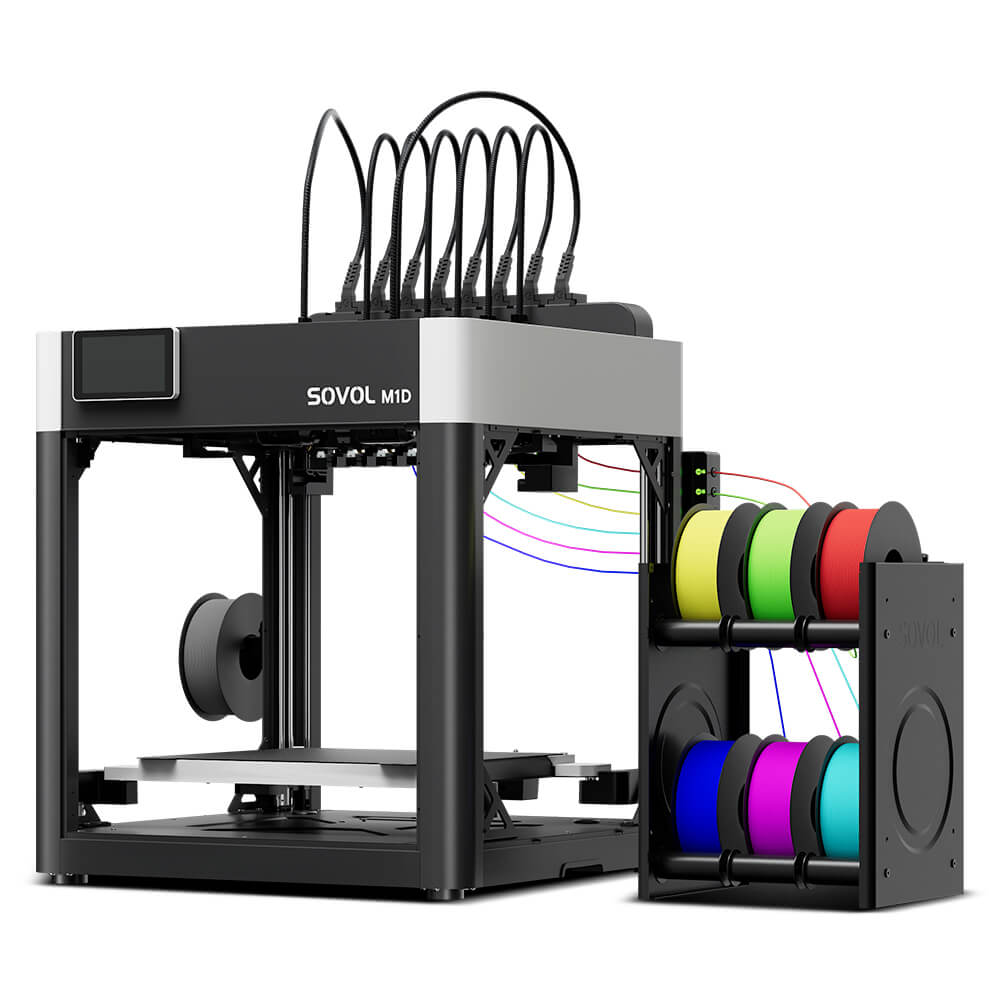
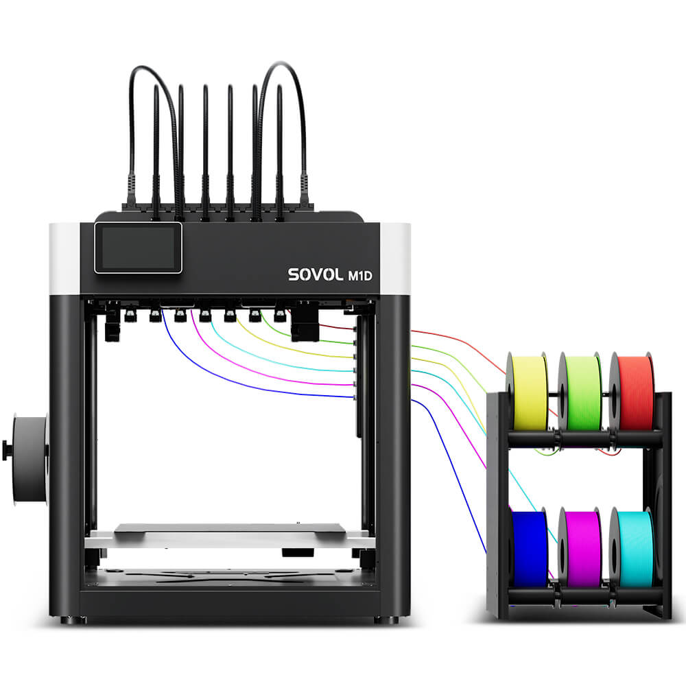
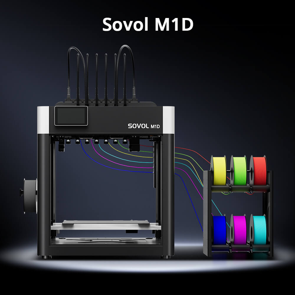
Multi-material or multi-color prints. Infill interacts with tool changes and purge waste, so a fast pattern still spends time on every color switch and the savings may be small relative to the total. On a multi-toolhead machine such as the Sovol M1D, where multiple toolheads can remain available for different materials or colors, the balance shifts — but the infill decision comes down to the same trade-offs.
Why Walls and Geometry Often Matter More Than Infill
This is the correction most infill guides bury: increasing infill alone does not guarantee a stronger part.
Outer walls carry much of the bending and tensile load, because they sit farthest from the neutral axis and form a continuous solid shell. Layer orientation decides where a part fails — a part loaded across layer lines can split at the layer bonds regardless of what fills its interior. Model geometry concentrates stress at sharp corners, thin necks, and unsupported spans no matter what the infill looks like.
The practical consequence: on many functional parts, adding perimeters or reorienting the print changes strength more than raising density from 15% to 40%. Infill still supports top surfaces and contributes to stiffness, but it is one factor among several, not a strength dial.
Checking Infill in the Slicer Preview Before You Print
The slicer preview is where infill decisions become visible. A quick check can help reveal avoidable toolpath and infill problems before printing. For a full routine, see Sovol's guide on how to read a 3D printer slicer preview.
- Does the pattern reach the walls? Check that infill lines connect to the perimeters. If they float free, look at infill-to-wall overlap and infill anchor settings.
- Are there unsupported top surfaces? Scrub to the first solid top layer and look underneath. A wide empty span is where sag will appear.
- Any sparse areas or internal gaps? Look for holes inside the part where infill should be. Gaps usually mean density is too low or overlap is too small.
- Is the infill applied to the intended regions? Modifiers, per-part settings, and height ranges can override the global pattern. Confirm the right infill is active where you expect it.
- What do the estimates say? Check the material and time readout, and expand the feature breakdown to see how much time infill actually consumes.
If the part has bridges or thin walls, the related guides on 3D printing bridges, thin-wall printing, tolerances and clearances, and support settings cover the adjacent settings that interact with infill.
A Simple Test-Print Workflow
Replace guesswork with your own data in five steps:
- Pick a representative model or test coupon. Choose something that resembles the real part's load case — a small bracket, a flat plate, or a compression cube.
- Change one variable at a time. Test pattern first, then density, then wall count. Changing several at once makes the result impossible to interpret.
- Compare the results side by side. Print at least two variants so you have a baseline.
- Measure what matters. Weigh each part, test rigidity by hand, note the print-time estimate, and inspect surface quality.
- Record the settings and outcome. Write down pattern, density, walls, material, and result so the finding carries to future projects.
A coupon only predicts behavior for geometry and orientation similar to itself. A flat plate tells you about flat plates, not about a bracket loaded on edge.
Troubleshooting Common Infill Problems
Infill does not connect well to walls. Check infill-to-wall overlap and infill anchor. Too little overlap leaves the sparse structure floating free of the shell.
The part is heavier than expected. Look at wall count, shell thickness, and whether a modifier or per-part setting is overriding your density. Solid shells often account for more weight than the infill does.
The print takes too long. Expand the time breakdown to see where the time actually goes. If infill dominates, try a simpler pattern or lower density. If walls or supports dominate, infill is not the bottleneck.
Infill creates visible vibration or noise. Grid and triangle-based patterns may increase the chance of raised intersections, noise, or nozzle contact on some setups. Gyroid can also vibrate at high density and speed. Try a non-crossing pattern or reduce speed.
Internal gaps appear in the preview. Raise density, increase overlap, or check that the pattern is actually applied to the region you are inspecting.
A part is still weak despite high infill. Stop adding density. Look at wall count, print orientation, layer adhesion, and material instead — those are the more likely causes.
FAQ
What is the best infill pattern for 3D printing? There is no universal answer. Gyroid, cubic, and triangles are common test points for functional parts, while lines and lightning suit decorative work. The choice depends on geometry, load direction, and what you're optimizing for.
Does higher infill make a print stronger? Sometimes, with diminishing returns. Past a moderate density, the added weight and time usually outweigh the gain.
How much infill is suitable for functional parts? Around 20–40% is a reasonable starting point to test from. Thin parts may need more walls rather than more infill.
Is Gyroid infill always better? No. It gives a more balanced internal structure and avoids in-layer crossings, but it produces more complex G-code and can vibrate at high density and speed.
Should I increase infill or wall count first? For load-bearing parts, walls usually come first. Adding perimeters puts solid material where bending and tensile loads are carried.