




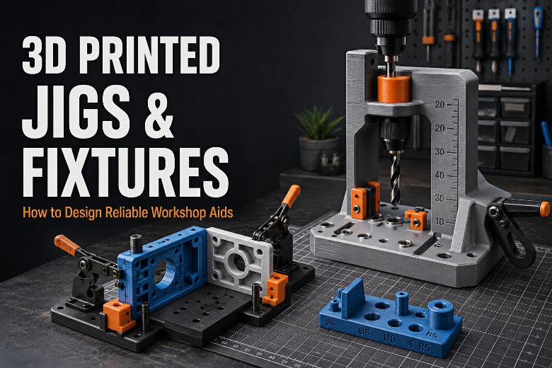
A well-designed printed aid gives you two things manual work can't: consistent positioning and reliable repetition. Whether you're drilling, gluing, soldering, assembling, routing, or inspecting, a small custom tool locks the workpiece and your process into the same relationship every time. And because you can revise and reprint it in an afternoon, it adapts as your project does. This guide covers what jigs and fixtures are, when they earn a place on your bench, how to design them, which materials and settings to reach for, and how to validate the final tool before relying on it.
Key Takeaway: A reliable 3D printed jig or fixture is designed around one specific task and validated with test prints — the "right" clearance, wall count, and material depend on your printer, your part, and how the tool is loaded.
Jig vs. Fixture: Two Jobs, One Workbench
Two terms get used interchangeably, but they describe different jobs. A jig guides the tool. A fixture holds the part. A drill jig steers a bit into the exact spot on every piece; an assembly fixture cradles and locates a workpiece so you can work on it.
The line blurs quickly — many printed tools do a bit of both, guiding a tool and holding a part at once. Terminology also varies between workplaces: an automotive shop may call anything that holds a body panel a "jig," while a machine shop reserves the word for tool-guiding. Don't get hung up on the label. Focus on what the tool actually does on your bench.
When 3D Printed Jigs and Fixtures Earn Their Place
Printed tooling isn't always the answer, but these custom 3D printed jigs and fixtures are genuinely strong in several common situations.
Prototyping and One-Off Proofs
When you're still figuring out a process, a printed aid is a fast, cheap way to prove a step before committing to metal tooling. Test an assembly sequence or hole pattern, find what's awkward, and change the design in minutes.
DIY Repairs and Workshop Projects
Refitting a worn part or building a jig that suits your own machinery is where printed aids shine. Drill guides, featherboards, zero-clearance inserts, stop blocks, and centering guides are bread-and-butter workshop tools.
Small-Batch Production
If you're running a handful to a few dozen identical parts, a printed fixture removes setup drift between pieces and keeps quality consistent. It suits the part-specific tooling that small-batch production relies on.
Assembly and Alignment Tasks
Positioning parts square, holding halves flush, or keeping a subassembly oriented while fasteners go in are exactly what a fixture does best.
Temporary or Frequently Revised Setups
Because a printed aid is cheap to reproduce, you reprint rather than re-machine when the process changes.
When a Printed Tool Won't Cut It
Know when not to reach for FDM. Printed plastic isn't a substitute for certified industrial tooling in demanding conditions. Avoid it where very high loads would bend or fracture the tool, where extreme temperatures exceed the material's limits, or where harsh chemicals would degrade the plastic. The same applies to safety-critical components and jobs requiring strict industrial certification or traceable, qualified tooling — a print without documented material and process validation isn't an acceptable replacement.
That's not a reason to avoid printed tooling; it's a reason to be honest about where it fits. For low- to moderate-load, temperature-moderate workshop and assembly work, an FDM aid is often ideal.
How to Design a 3D Printed Jig: Key Principles
Whether you're building a 3D printed fixture or a tool-guiding jig, the dependability of the result comes from a few design choices repeated across good examples.
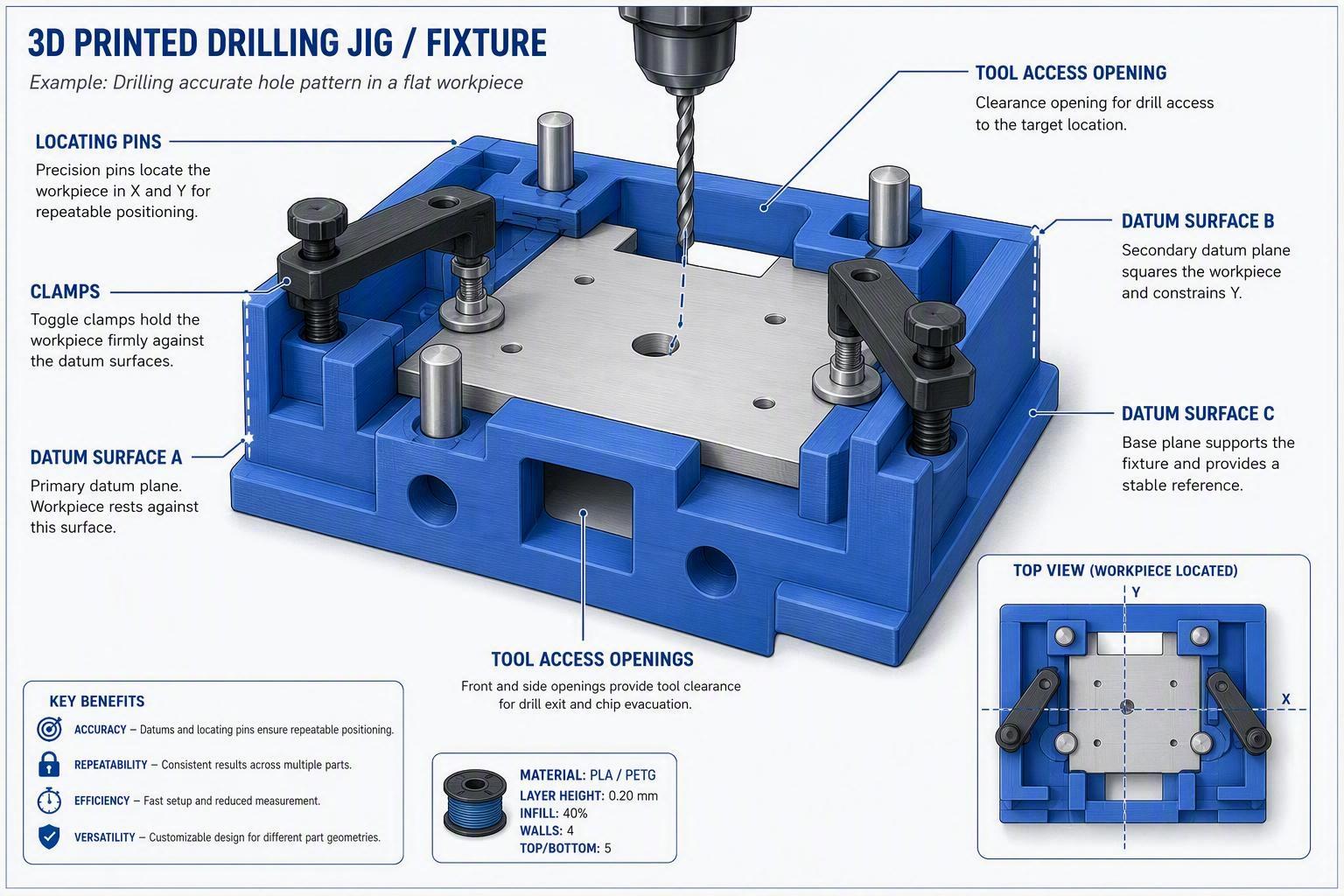
Reference surfaces and datums. Start from a clean reference. Pick one or two flat, machined (or printed-then-flattened) surfaces as datums and locate the workpiece against them. Everything else hangs off those planes.
Locating pins and alignment features. Pins, dowels, keys, and pockets give the part a positive, unambiguous seat. An asymmetric pattern makes wrong loading impossible or at least obvious.
Stops and guides. Positive stops prevent the part sliding past position; guides steer a tool or edge instead of relying on the operator's eye.
Clamping and retention. Clamps should usually press the part against locating features rather than determine its position by themselves. If the tool must resist push or drill forces, build clamping into the body — slots for hardware, screw bosses, or printed threads and screws.
Clearance for the workpiece. The part has real dimensions and real tolerance too. Leave room to drop it in and lift it out — a too-tight pocket is a common reason a "perfect-fit" tool is unusable.
Access for tools and fasteners. Leave space for the drill, driver, gauge, or hand that must reach the work.
Easy part removal. Add a thumb hole, finger slot, or push-out port so parts come out cleanly instead of being pried and scraped.
Rounded corners and stress relief. Sharp internal corners concentrate stress and crack under repeated loading. Fillet corners, especially where the tool bears force, and add ribs or gussets in high-stress areas.
Symmetry and repeatability. Make locating schemes symmetrical or clearly keyed so the operator can't invert the part. Repeatability is the whole point.
How Tolerance, Clearance, and Print Settings Shape Performance
Printed dimensions may differ from CAD, especially for holes, thin walls, and features affected by cooling or line placement, and for 3D printed manufacturing tools those deviations decide whether the tool works.
Tolerance and clearance. Your printer holds some dimensions tighter than others, and internal holes can print undersized because of line width, extrusion flow, and perimeter placement. Start from clearances your machine actually holds and verify them — our FDM tolerances and clearances guide gives sliding, press, and loose-fit starting values. Treat any number as a starting point, not a guarantee.
Print orientation and layer direction. Layer-to-layer strength may be lower than strength along continuous perimeters, but actual performance depends on the material, geometry, orientation, and print settings. Orient holes to print cleanly and align load paths with the stronger direction — the same logic you'd apply to any functional print, from gears to brackets.
Walls, perimeters, and infill. Adding perimeters can improve rigidity and edge strength, but the best balance depends on the geometry, material, and loads applied to the tool. The right values aren't universal — they depend on your nozzle, layer height, and the force the tool sees. Start conservative and test.
Choosing a Material for the Working Environment
There's no single best filament. The choice follows the environment the tool lives in, and the values below are typical starting points — actual results depend on your filament, printer, and settings.
Heat-related values are approximate material-property references, not guaranteed working temperatures. Actual performance depends on load, geometry, print orientation, wall structure, settings, and the specific filament formulation.
|
Material |
Stiffness |
Approximate softening reference |
Toughness |
Outdoor/UV |
Ease of printing |
Best-fit role |
|---|---|---|---|---|---|---|
|
PLA |
High |
Low (~55–60 °C) |
Low (brittle) |
Poor |
Easiest |
Indoor templates, drill guides, light positioning aids |
|
PETG |
Medium |
Moderate (~75–80 °C) |
Good |
Moderate |
Easy |
General shop work, clamps, reusable fixtures |
|
ASA |
Medium–high |
High (~95–105 °C) |
Good |
Excellent |
Harder (warp) |
Outdoor/UV-exposed tools, warmer areas |
|
ABS |
Medium |
High |
Good |
Poor |
Harder (warp) |
Indoor heat/impact where an enclosure is available |
|
Nylon / CF-nylon |
High |
Moderate–high |
Very good |
Depends on the formulation; nylon can also absorb moisture and may require careful storage |
Hardest |
Heavily loaded or wear-prone tooling |
As a rough rule: choose PLA for a stiff, easy, indoor light-duty aid; PETG for a tough, all-around 3D printing workshop tool; ASA when the jig sits in sunlight or near heat and needs to survive outdoors; and filled nylon when it takes real load or repeated wear. Match the material to where the tool works, not to the most impressive spec sheet.
Practical 3D Printing Workshop Tools to Try
These examples map to real bench tasks and show the design principles coming together.
Drill guides and jigs. A block with a pilot hole sized to your bit keeps holes straight and evenly spaced. Add a flat datum and a stop so it indexes off the workpiece edge.
Printed guides can wear during repeated or high-force operations. For repeated drilling, consider using a metal bushing. Do not rely on a 3D printed guide as the only safety guard for high-speed cutting operations, and always secure the workpiece and follow the tool manufacturer's safety instructions.
Assembly alignment fixtures. A cradle that locates two or more parts flush against datums and pins so you can drive fasteners without shifting.
Soldering and electronics holders. A stand that grips a PCB, connector, or wire at a comfortable angle, freeing both hands and holding the joint steady. Keep the soldering iron away from the printed body, and choose a material and design that suit the heat exposure.
Gluing clamps and positioning aids. Corner blocks, right-angle brackets, or alignment guides hold panels square while adhesive sets.
Repeated measurement templates. A gauge or template with slots and holes lets you mark or measure the same features quickly.
Cutting and routing guides. Straight edges, circle guides, and template followers steer a router or knife along a consistent path.
Small-batch inspection fixtures. A go/no-go gauge or a cradle that seats a part against reference pins checks a critical dimension fast.
A Step-by-Step Workflow for Designing a Printed Tool
Iterate rather than aiming for perfection on the first shot.
- Define the task and required accuracy. Write down what the tool must do, how accurately, and how often.
- Measure the workpiece. Use calipers on the real part and record actual dimensions, not nominal ones.
- Create the first CAD model. Model a clean datum, locating features, and the features that do the work.
- Add clearances and access areas. Build in room to insert/remove the part and reach it with tools.
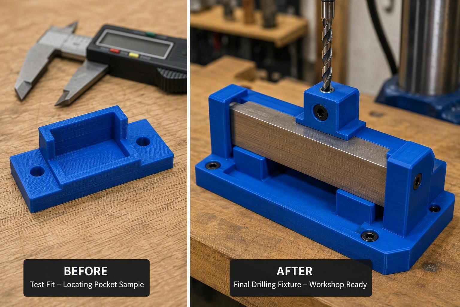
- Print a small test section. Print only the critical portion — a locating pocket or guide hole — to check fit early.
- Test the fit and function. Try the section with the actual workpiece and the actual tool.
- Revise the design. Adjust clearances, walls, orientation, or locating geometry from what you measure.
- Print the final jig or fixture. Reprint the full tool and re-test it before real work.
Troubleshooting Common Problems
|
Problem |
Likely cause |
Practical fix |
|---|---|---|
|
Workpiece doesn't fit |
Clearance too tight; wrong measurement; warped print |
Measure again; add insertion clearance; reprint flat; chamfer lead-in |
|
Tool is too loose |
Clearance too large; under-extrusion; wrong scale |
Reduce modeled clearance; calibrate flow; check scale/units |
|
Fixture cracks |
Sharp corners; thin walls; overloading; brittle material |
Fillet corners; add walls/ribs; use PETG/ASA/nylon |
|
Part shifts during use |
Poor clamping; wrong orientation; forces not directed into the locating features |
Clamp against locators; orient load into strong direction |
|
Tool can't reach the work area |
Access clearance too small |
Move clamps/stops; open up the working area |
|
Tool deforms from heat |
Material below operating temperature |
Choose a material whose tested temperature capability matches the actual load and environment. PETG or ASA may help in some cases, but neither is a universal solution |
|
Parts not aligned consistently |
Poor datum surfaces; excessive clearance or side play; dirty contact surfaces |
Flatten datum faces; add pins/keys; clean contact points |
A Checklist for Design and Testing
Run through this before a tool is done:
- Task and accuracy defined in writing
- Workpiece measured with calipers
- Reference datum surfaces established
- Locating pins, keys, or stops added
- Clearance for insertion and removal built in
- Room for tools and fasteners confirmed
- Clamping holds the part against the locators
- Corners filleted and stress risers removed
- Print orientation aligns load with strong direction
- Walls, perimeters, and clearances suited to the material
- Small test section printed and fit tested
- Warpage and elephant's foot checked
- Full tool printed and re-tested with the real workpiece and tool
- Repeated across several identical parts to confirm consistency
FAQ
Do I need a special printer or material for jigs and fixtures?
No. A calibrated FDM printer with PLA or PETG covers most workshop aids. Save tougher materials like ASA or filled nylon for outdoor, hot, or heavily loaded tools.
What's the best material to start with?
PETG is a solid general-purpose choice for functional shop tools — tougher than PLA and easy to print. PLA is fine for light indoor guides and templates.
How much clearance should I add to a locating pocket?
Start small and test. FDM holes tend to print slightly undersized, so err on the side of a little extra clearance and verify with a printed test section instead of guessing one number.
Can I print a jig to drill metal?
A printed guide can start holes in metal at low-to-moderate loads, but it will wear and won't hold up to hard or high-speed drilling. Add a steel bushing for repeatability.
Is a 3D printed fixture accurate enough for inspection?
A printed fixture may be suitable for informal or process checks after it has been validated against a known reference. It should not replace calibrated measurement equipment where safety, certification, or strict quality control is involved.
Conclusion: Design Around the Task, Then Validate
A 3D printed assembly aid is most useful when it's built around one specific job and proven with test prints. Define what the tool must do, model it against real measurements, give it clear datums and locating features, pick a material that matches the environment, and verify the fit with a small test section before relying on it. Done that way, a printed aid quietly removes the guesswork from drilling, gluing, soldering, assembly, and inspection — and because you can reprint any revision, it keeps improving alongside your work.
For more ways to keep functional FDM parts reliable, browse the rest of the engineering guides on the SOVOL blog — from snap-fit joints for one-piece fastening to threads, gears, and clearance guidance.