




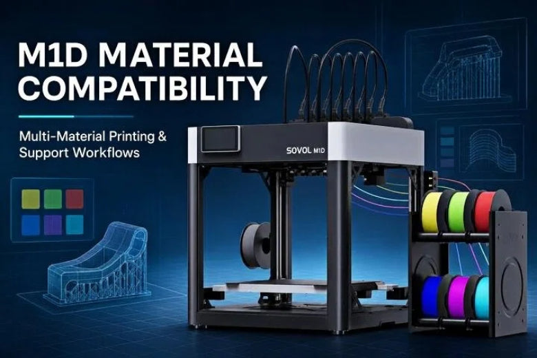
Key Takeaway: Successful multi-material 3D printing depends on matching polymer thermal dynamics, glass transition temperatures, and inter-layer bonding characteristics rather than simply selecting matching filament colors.
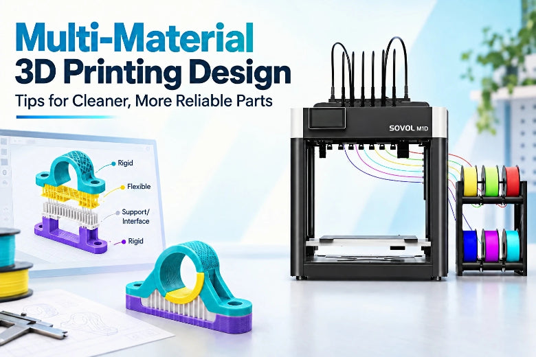
Multi-material FDM printing expands desktop manufacturing by allowing makers, engineers, and educators to combine rigid polymers, flexible elastomers, and breakaway or soluble support filaments in a single automated job.
However, forcing different filaments into a single print introduces complex physical challenges. Polymers differ in melting temperatures, glass transition behaviors (Tg), thermal shrinkage rates, and surface adhesion characteristics. Pairing incompatible materials causes delamination, severe corner warping, clogged hotends, or failed prints.
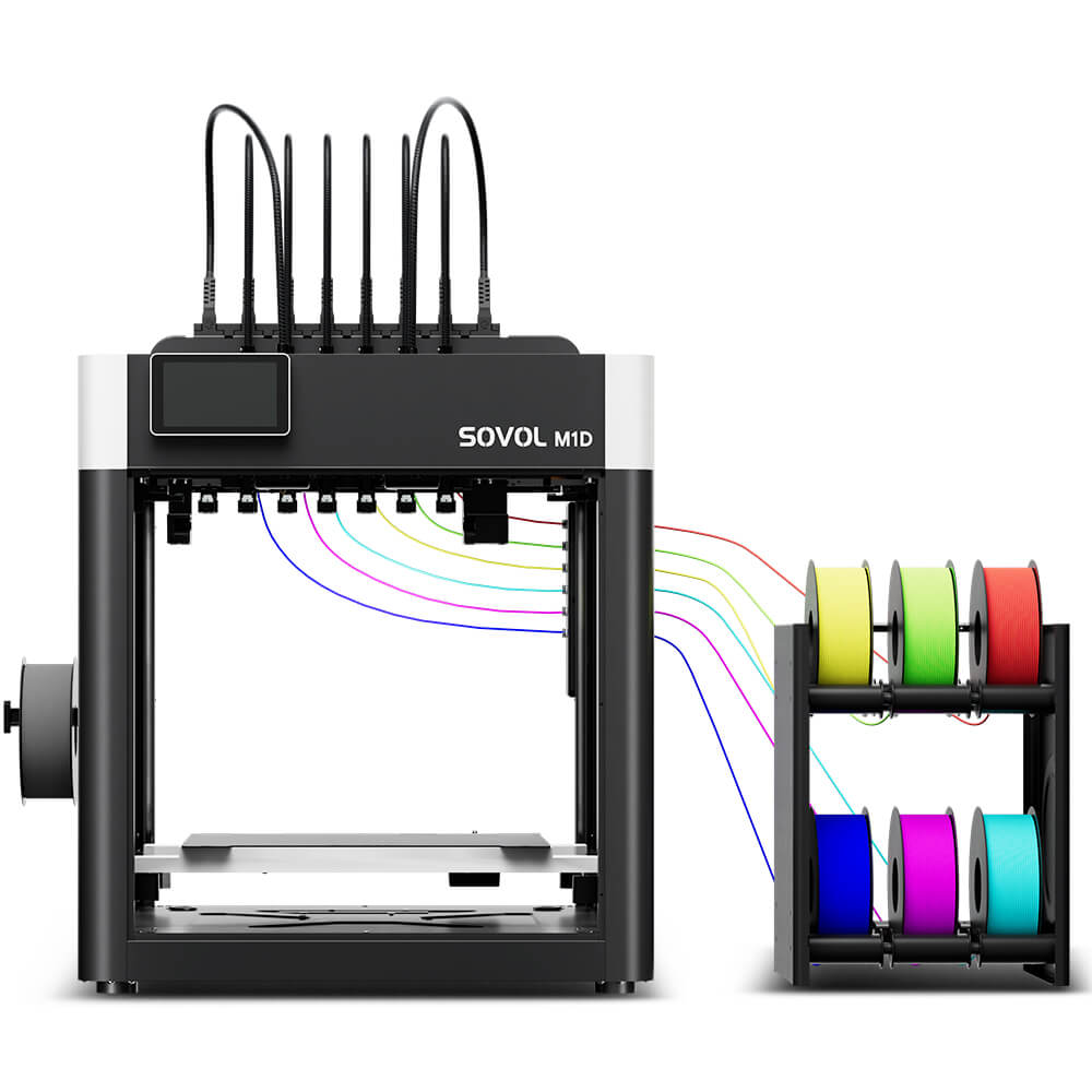
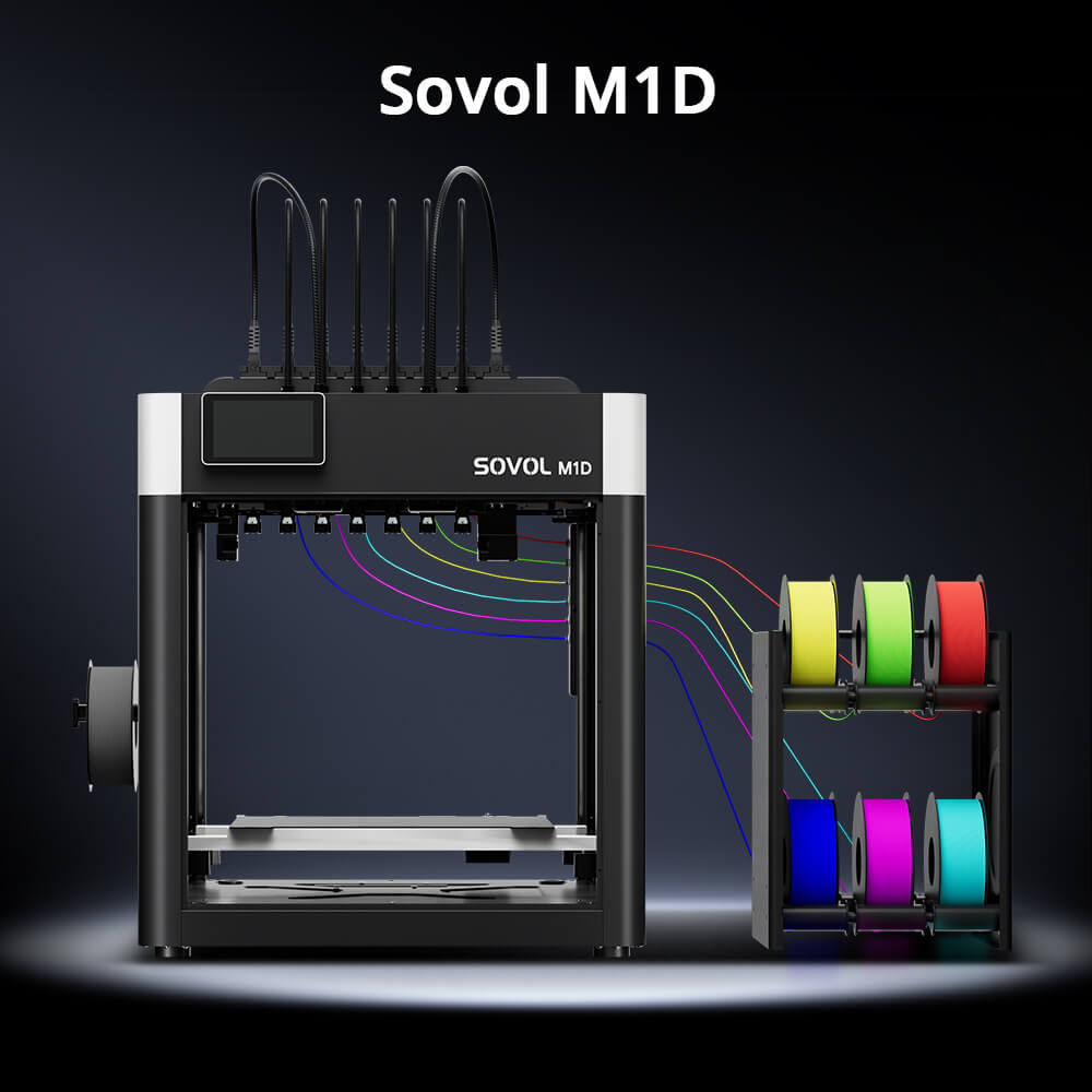
The Sovol M1D addresses these challenges using Sovol's DualX system—a hybrid independent dual extruder (IDEX) and automated tool-changing gantry. Mastering M1D material compatibility, support selection, and toolhead calibration enables reliable production while avoiding costly material failures.
How the M1D Tool-Changing Workflow Works

Traditional multi-material printing relies on single-nozzle swappers that retract, cool, feed, and purge hundreds of millimeters of filament into a purge block during every color change. This process creates significant material waste, extends print times, and subjects materials to repeated thermal cycles.
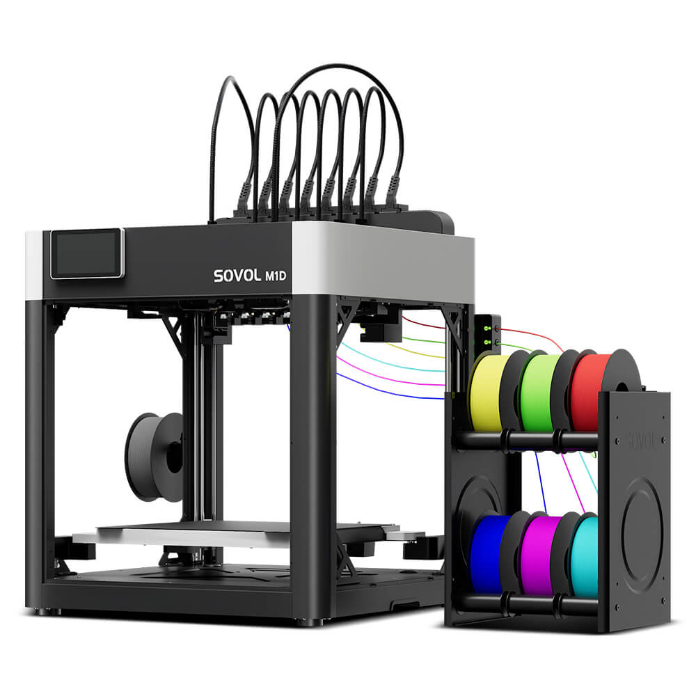
The Sovol M1D utilizes a hybrid IDEX tool-changing architecture. Rather than routing filaments through one nozzle, the DualX system pairs one fixed primary toolhead on the main carriage with an automated parking dock housing swappable secondary toolheads.
Fixed Primary Toolhead (Carriage Left) <- → Swappable Secondary Toolheads (Parking Dock Right)
Toolhead 2 (Secondary Color / Material)
Toolhead 3 (Dedicated / Soluble Support)
Toolheads 4–7 (Additional Channels)
- 1+6 DualX Tool-Changing System: Features 1 fixed primary toolhead paired with 6 swappable toolheads (supporting up to 7 total colors or materials in a single build job).
- High-Temperature Hotends: Features a maximum nozzle temperature of 300°C with standard 0.4mm hardened steel nozzles.
- Heated Build Plate: Supports heated bed temperatures up to 100°C for reliable adhesion across various filaments.
- Rapid Toolhead Swapping & Preheating: Official manufacturer specifications claim a 5-second toolhead swap time with independent nozzle preheating between active and parked bays.
- Filament Automation: Includes a 6-channel Automatic Filament System (AFS) for automated loading and runout detection.
- Near-Zero Purge Waste: Near-zero purge waste during material transitions compared to single-nozzle swappers, through prime towers or wipe sequences in slicer settings still generate minimal waste.
M1D Operational Modes & Build Volume Specifications
The M1D operates across multiple modes with specific build dimensions for each configuration:
- Single Mode: 300 × 300 × 350 mm — Uses one toolhead across the maximum build volume.
- Dual Overlap / 7-Head Mode: 240 × 300 × 350 mm — Allows toolheads to operate with overlapping paths across the bed for multi-material jobs.
- 6-Toolhead Switching Mode: 300 × 300 × 350 mm — Swaps up to 6 secondary toolheads across the full build area.
- Copy Mode (Duplication): 178 × 300 × 350 mm — Operates two toolheads in parallel across the X-axis to print identical twin parts. (Note: While 180mm is the physical limit per side, staying within 178mm prevents part overlap).
- Mirror Mode: 140 × 300 × 350 mm — Synchronizes toolheads in reverse motion across X-axis halves to print mirrored left/right parts.
Technical Note: Copy and Mirror modes can increase throughput for suitably sized parts by dividing bed width between extruders; they do not increase the printer's total physical bed size.
For additional analysis, explore our IDEX vs tool changer technical breakdown and our complete guide to Copy Mode 3D printing workflow.
Understanding Different Material Roles

Operating an IDEX tool-changing 3D printer effectively requires assigning clear functional roles to each active toolhead:
- Primary Model Material: The core structural polymer (e.g., PLA, PETG, ABS, ASA, PA, PC, PLA-CF, or PETG-CF) determining overall part strength, heat resistance, and geometry.
- Secondary Model Material: Used for multi-color details, branding, or complementary properties. Must form a strong chemical or mechanical bond with the primary material.
- Dedicated Support Material: Specialized filament engineered to build support scaffolds beneath severe overhangs. Dedicated support materials may be designed to dissolve in water or another specified solution, while others are intended to break away mechanically. Always check the material manufacturer’s instructions.
- Interface Material: Model-compatible polymer used only at the 1–3 contact layers touching the part. Printing bulk supports in cheap filament and using specialized material only at the interface drastically lowers costs.
- Flexible or Soft Material: Elastomeric polymers (like TPU) deposited into rigid body recesses for integrated gaskets, living hinges, or non-slip grips.
Evaluating Filament Compatibility for Multi-Material 3D Printing
Before assigning two spools to a multi-material job, evaluate their physical compatibility using this 7-point checklist:
- Nozzle Temperature Window: Ensure printing temperatures overlap or stay within manageable idle standby ranges across active toolheads.
- Heated Bed Temperature: Materials sharing the build plate in a single job must adhere at the same bed temperature. Pairing PLA (50°C bed) with ABS (100°C bed) on the same plate is not feasible.
- Thermal Contraction & Shrinkage: High-shrinkage polymers (ABS, Nylon) warp significantly as they cool. Pairing high-shrinkage and low-shrinkage materials causes layer shear along bond lines.
- Inter-Material Chemical Adhesion: Chemically similar polymers bond strongly across layers. Dissimilar polymers (PLA and PETG) exhibit poor adhesion—a flaw for structural joints, but an asset for zero-gap support interfaces.
- Moisture Sensitivity: Hygroscopic materials (such as PVA or Nylon) absorb atmospheric moisture rapidly, causing bubbling and poor adhesion. They should be dried and fed from dry storage or dry boxes.
-
Nozzle Material Requirements: Abrasive composite filaments (such as PLA-CF or PETG-CF) require hardened steel nozzles (which come standard on the M1D) to prevent orifice wear.
-
Chamber Environment: High-temperature engineering materials (ABS, ASA, PA, PC, PLA-CF, PETG-CF) benefit from bed adhesive/glue, enclosure panels, or active chamber heating modules to maintain ambient warmth and prevent corner warping.
Selecting 3D Printing Support Materials and Interface Strategies
Choosing effective 3D printing support materials and slicing strategies reduces post-processing labor and preserves surface finish.
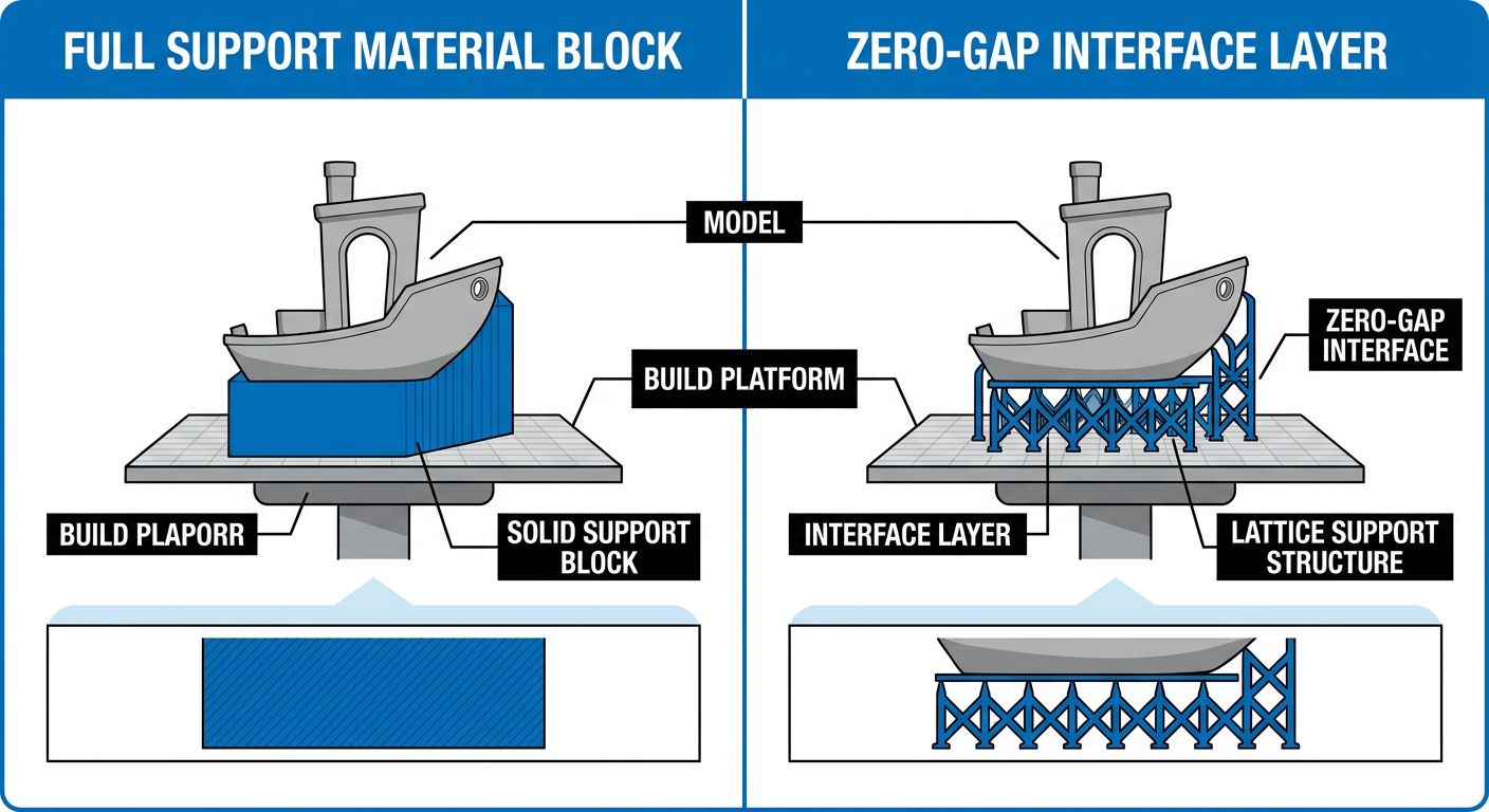
Figure 2: Support interface strategy using a non-bonding material at contact layers versus printing full support structures.
Support Strategy Comparison
|
Support Strategy |
Best Material Pairings |
Surface Finish Quality |
Post-Processing Effort |
Thermal & Environmental Constraints |
|---|---|---|---|---|
|
Same-Material Breakaway |
PLA + PLA, PETG + PETG |
Moderate (leaves minor scars) |
Manual removal with tools |
Shares identical bed and nozzle temperatures. |
|
Dedicated Breakaway Filament |
PLA + Support Filament |
High (clean bottom surface) |
Easy manual peeling |
Requires matching bed temperature. |
|
Soluble Support Material |
PLA + PVA |
Pristine (complex cavity support) |
Water bath dissolution |
PVA is moisture-sensitive and requires dry storage. |
|
Cross-Material Interface Layer |
PETG Model + PETG/PLA Interface |
High to Pristine |
Easy manual separation |
Requires compatible bed temperature settings. |
Support Rules:
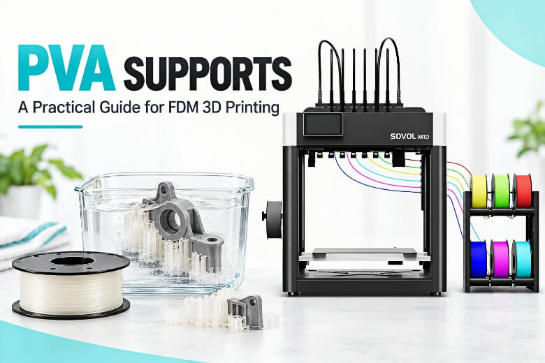
- Soluble Support Material (PVA): Dissolves cleanly in water, making it ideal for intricate internal cavities and complex overhangs.
- Breakaway Interface Strategy: Printing the bulk support structure in cost-effective main filament and switching toolheads only for the top interface layers significantly reduces tool swaps and material consumption while maintaining smooth contact surfaces.
For broader hardware context, consult our best multi-material 3D printers guide.
Choosing Materials for Practical Multi-Material Workflows
Sovol’s M1D product presentation highlights several key multi-material workflows, including PETG support, PLA with PVA water-soluble support, and PLA with TPU combinations. Actual results may vary depending on the filament brand, material profile, moisture condition, and toolhead calibration. Always test each new material pairing with a small test print before launching a large build job.
-
Multi-Color Decorative Prints (PLA + PLA) —
Featured in Sovol's M1D Product Materials
Assigning different PLA colors across toolheads can work well with compatible profiles because loaded spools typically use similar settings, though users should verify each filament profile before printing. -
Rigid Model with Soluble Supports (PLA + PVA) —
Featured in Sovol's M1D Product Materials
Toolhead 1 prints PLA while Toolhead 2 deposits PVA soluble support. Soaking the completed print in warm water can simplify support removal and reduce surface damage. -
PETG with Dedicated Support Material —
Featured in Sovol's M1D Product Materials
PETG models paired with dedicated support materials can improve overhang quality and ease post-processing. Compatibility depends on the selected support filament and slicer profile. -
Rigid Body with Flexible Elements (PLA + TPU) —
Featured in Sovol's M1D Product Materials
PLA + TPU is featured in Sovol’s M1D product materials for creating rigid bodies with integrated flexible gaskets or grips. (Note: PETG + TPU should be treated as a pairing that requires additional testing). -
High-Temperature Engineering Parts (ABS, ASA, PA, PC, Carbon-Fiber Filaments) —
Requires Material-Specific Testing
High-temperature materials (ABS, ASA, PA, PC, PLA-CF, PETG-CF) can be printed using standard 0.4mm hardened steel nozzles (300°C max) and a 100°C heated bed, recommended in combination with bed adhesive, enclosure panels, or active chamber heating modules. -
Batch Production & Symmetrical Parts (Copy & Mirror Modes) —
Recommended Workflow
Utilize Copy Mode (up to 178mm width) for duplicate parts, or Mirror Mode (up to 140mm width) for symmetrical left and right enclosure components.
To compare tool-changing flexibility with large-format single-extruder setups, read our Sovol SV08 Max vs M1D comparison.
Tool-Change Calibration and Print Preparation
Precise calibration prevents layer shifting, stringing, and nozzle collisions across active extruders.
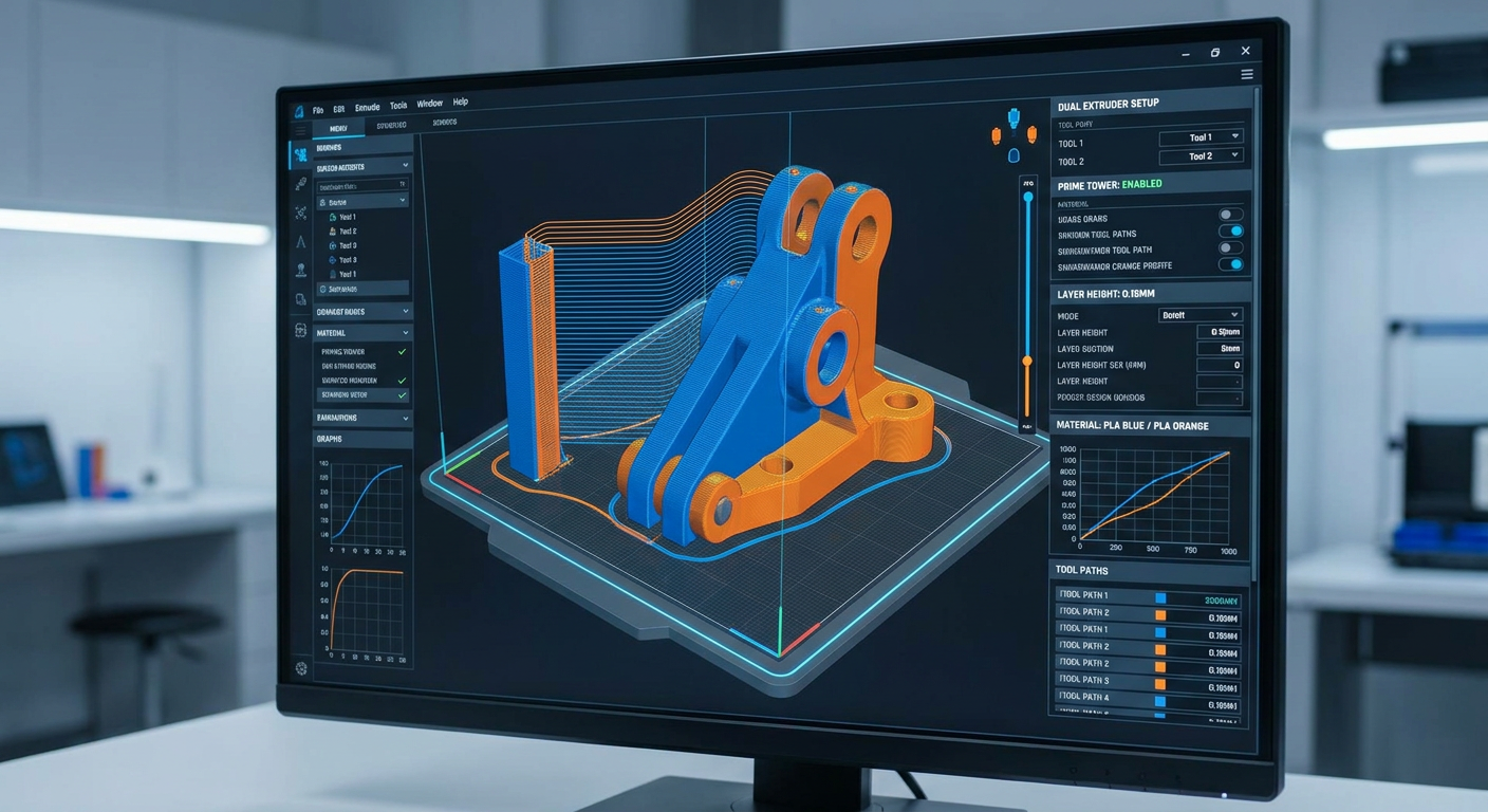
Figure 3: Slicer preview displaying toolhead material assignments, tool path trajectories, and prime tower layout.
Essential Calibration Procedures
- Automated Vision XY Offset Alignment: The M1D uses automated calibration features, including camera-assisted vision alignment, to register exact spatial offsets between toolheads.
- Z-Height Probing: Ensure all active toolhead nozzles align to identical Z-height baselines to avoid bed scratching or uneven first layers.
- Filament Drying Protocols: Dry moisture-sensitive PVA and Nylon spools in a filament dryer before printing, and feed them from dry storage or dry boxes.
- Nozzle Cleanliness & Standby Temps: Use the recommended standby-temperature and extrusion-temperature ranges for the selected filament in the slicer (avoiding one fixed value for every material) and clean nozzle tips to prevent oozing.
- Prime Tower Setup: Enable a prime tower on the build plate to restore consistent extrusion and nozzle pressure after a tool change.
- Slicer Preview Verification: Inspect the sliced G-code preview layer-by-layer to confirm toolhead numbers match assigned material roles.
Common Problems and Troubleshooting
Issue 1: Layers Delaminating Between Model Materials
- Root Cause: Low chemical affinity or insufficient extrusion temperature.
- Solution: Ensure materials are chemically compatible, adjust extrusion temperatures within recommended limits for the secondary filament, or add mechanical keying features.
Issue 2: One Material Warping While the Other Stays Flat
- Root Cause: Bed temperature set incorrectly for high-shrinkage polymers.
- Solution: Avoid combining polymers with conflicting bed temperatures. Use enclosure panels, bed adhesive, or active chamber heating modules for ABS, ASA, PA, or PC.
Issue 3: Stringing and Filament Blobs During Tool Swaps
- Root Cause: Parked toolheads idling at full printing temperature or wet filament.
- Solution: Enable standby temperature reduction in your slicer and thoroughly dry spools before printing.
Issue 4: Support Material Fusing Permanently to Model
- Root Cause: Incorrect support interface gap settings or excessive nozzle temperature.
- Solution: Adjust support Z-distance in your slicer, or use dedicated non-adhering support/interface materials.
Issue 5: Toolhead Collides with Printed Model
- Root Cause: Incorrect Z-offset or missing travel Z-hop on tool changes.
- Solution: Re-calibrate nozzle Z-offsets and enable travel Z-hop during toolhead moves in the slicer.
Practical Pre-Print Checklist
- Verify Thermal Compatibility: Confirm loaded filaments share compatible bed temperature requirements.
- Dry Sensitive Filaments: Dry PVA and Nylon spools thoroughly before starting.
- Check Nozzle Types: Assign abrasive composite filaments (PLA-CF/PETG-CF) to standard hardened steel nozzles.
- Run XY and Z Calibration: Execute automated vision alignment and Z-offset probing across active toolheads.
- Clean Nozzle Tips: Remove hardened residue from parked nozzle tips.
- Configure Standby Temps: Confirm in slicer settings that parked toolheads cool to idle temperatures.
- Enable Prime Tower: Include a prime tower to re-establish nozzle pressure following swaps.
- Inspect Slicer Preview: Verify toolhead numbers and support interface layers in the sliced preview.
Frequently Asked Questions (FAQ)
Can different materials be used in one M1D print?
Yes. The Sovol M1D's DualX system allows independent toolheads to deposit different materials in a single job, provided the filaments share compatible bed temperatures and thermal properties (e.g., PLA with PVA, or PETG with a PLA interface).
Can support material be combined with model material?
Yes. You can assign a dedicated support or soluble material to a secondary toolhead while printing the model body with structural filament. Using secondary material only at contact interface layers minimizes expensive support filament consumption.
Does tool-changing eliminate all filament waste?
While tool-changing drastically reduces waste compared to single-nozzle swappers by avoiding large purge blocks, it does not eliminate waste entirely. A small prime tower or wiping sequence is still required to re-pressurize nozzles after swaps.
Do Copy and Mirror modes increase the printer's build area?
No. Copy and Mirror modes operate both toolheads simultaneously by dividing the X-axis build width between them. While this doubles throughput for small-to-medium parts, it reduces the maximum printable width per part.
Why is calibration important for tool-changing toolheads?
Independent toolheads must align precisely in X, Y, and Z dimensions. Proper calibration prevents layer shifting between materials, rough surface finishes, or nozzle collisions during tool swaps.
How should users confirm material compatibility?
Users should evaluate three criteria: nozzle printing temperature window overlap, identical bed temperature requirements, and chemical or mechanical bonding behavior. Test new material pairings with a small sample print before launching large jobs.
Next Steps & Technical Resources
Optimizing your multi-material workflow requires matching polymer chemistry with precise tool-changing execution. To review complete hardware specifications, slicing profiles, and official documentation, visit the Sovol M1D official landing page.